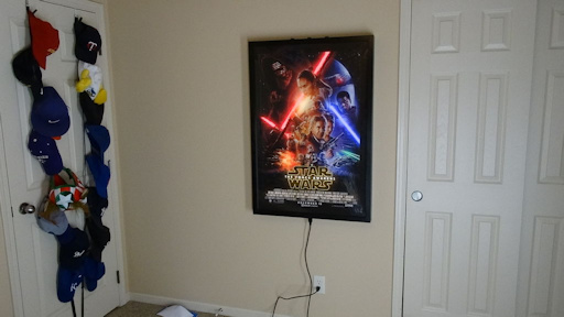
The Force Awakens Backlit Movie Poster Frame
This is a great way to add something very unique to your house. This movie poster frame looks like a normal frame with a movie poster in it, but is has some surprises up it's sleeve. This frame has a motion sensor and 172 RGBW LED lights to give the poster some animation effects. One of the best effects is the rainbow effect for the light sabers. Who doesn't like rainbows???
The poster has 3 black arcade push buttons on the top of the frame that allow the user to control the mode of operation, the brightness level of the LEDs, and the duration of time the display is on when activated by the motion sensor.
I also used a spreadsheet to generate the Arduino code for the lighting effects to save time and make it easier.
Here are the 8 different Modes of the display:
Motion Color - Motion activated color display.
On Color - Constant color display.
Motion White - Motion activated white back lighting.
On White - Constant white back lighting.
Motion Sabers- Motion activated light sabers only.
On Sabers - Constant light sabers only.
Motion Rainbow - Motion activated light saber rainbow effect.
On Rainbow - Constant light saber rainbow effect.
I've always wanted to make a backlit movie poster frame. I started looking for LEDs to use and came across addressable LED strips and thought it might be neat to use them to make the movie poster look animated. Then I realized I needed to find a movie poster with items in the poster that would look great and might have some kind of lighting effect or something that would glow. Since my kids really enjoyed The Force Awakens and our family members are Star Wars fans, I decided to go with The Force Awakens poster.
As you read through the Instructable think about the ways you could add lighting to one of your favorite movie posters or LED effects to something else in your house like a mirror or piece of furniture.

Step 1: Tools and Materials
Here are the materials and tools I used for this project. I have included affiliate links for some of the items for your convenience.
Materials
The materials I used on this project were as follows:
The Force Awakens movie poster from moviepostershop.com
1x6 poplar boards for the outline of the frame
1/2-inch plywood for the back board that the LEDs are attached to
Miscellaneous pieces of wood
1/8-inch thick acrylic sheeting for both sides of the poster
Screws of various lengths and types
Solder
Screw terminals
Arcade Pushbuttons
Electrical cords
Power plug
Wire
Resistors - 10K and 470 Ohm
Capacitors - 1000uF 10V
Hinges
Wood Glue
Stain
Wood Sealer
Tools
The tools I used on the project were as follows:
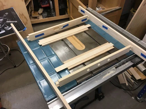
Table saw
Band saw
Cordless drill
Drill press
Random orbit sander
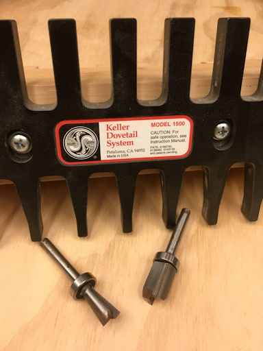
Router with dovetail jig
Sand paper and sanding blocks
Screwdrivers
Soldering Iron
Clamps
Not all of the tools in this list are required, but will make the construction much easier. Your build may need more or less than what I show. This may also vary based on the material that you construct your marble track and cabinet with.
NOTE: If you plan on using any tool for a project please make sure you are familiar with the tool and all of the dangers associated with it. If you are not familiar with a tool then you should ask someone who is to show you the proper way to use it. A lot of communities have classes at local colleges on the proper use of tools and machinery. There are also local woodworking clubs that offer classes at very reasonable rates for beginners. I highly recommend using these resources for your safety and for the most efficient use of the tool.
SAFETY FIRST
Always wear eye and hearing protection. Always work safe with the proper safety equipment and guards on your tools.


Step 2: Designing the Poster Lighting Elements
I was trying to figure out a way to line up the LEDs with the items I wanted to light up in the poster. I realized the easiest way to do this was to make a black and white copy of the original poster that I could attach to the back of the poster frame and then mount the LEDs directly to it. That way when the poster was mounted in front of the LEDs then everything would line up perfectly.
I didn't want the poster frame to be sticking out from the wall very far so I hooked up a small section of LEDs and placed them on my kitchen table. Then I placed the real movie poster over the LEDs to find the distance the LEDs needed to be away from the poster. I didn't want the LEDs to be so close to the poster that they created an obvious hot spot and I didn't want them so far away the LED lights would start to spread and overlap with each other.
I settled on one inch of separation between the board the LEDs were mounted to the back of the plastic sheet that the poster was mounted between. That separation distance also worked well from a layout standpoint.
I thought about making partitions between areas of the poster with card stock or card board in order to separate the light between the elements. Using a small piece of poster board under the poster I realized that the effect was a very sharp shadow line that I didn't like so I scrapped that idea. In addition, it would have added a lot of work to the assembly.
Another thing I wanted for the poster frame was that there would only be one cord from the center of the bottom of the frame to power everything. I thought about running the electrical cord through the wall, but that seemed like overkill and would then mean a lot of extra work if I decided to move the poster.


Step 3: Frame Design
The outside of the frame is constructed from 1X4 poplar boards I picked up at a local lumber store. The final depth of the frame was 2-3/4". The slim profile of the frame became a slight challenge in trying to get all of the components to fit during the build, but it all worked out.
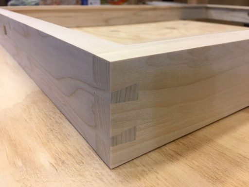
Frame corner joints
I wasn't sure how I wanted to make the corners of the frame. I thought about using pocket holes or maybe mitered corners with biscuits or splines. I decided to go with dovetail corners since I have a dovetail jig and thought they would be a nice look even though I had planned to stain the frame black. You could easily used a pocket hole jig to do this much faster.
Front Trim
I added 3/8-inch square strips of poplar to the front of the frame to serve as the restraint to hold the plastic sheeting in place in the frame. This was added once the entire outside 4 pieces of the frame were dovetailed and glued together.
Hanging system
I used a french cleat system to hang the frame. I made the cleat that attaches to the wall a couple inches shorter in width than the width of the poster frame so I can slide the frame left or right over a 2-inch width.
I also drilled several sets of holes in the cleat that attaches to the wall. There is a pair of holes at the center of the cleat and a pair one inch to the left and right of center. This, paired with the 2 inch width adjustment from the shorter width of the cleat on the wall allows for a width adjustment of 4 inches.
The cleat is also wide enough that if I need to hang the frame at a location without any wall studs then I should be able to drill holes near each edge of the cleat that would hit wall studs at a typical 16-inch spacing.
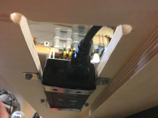
Power
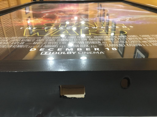
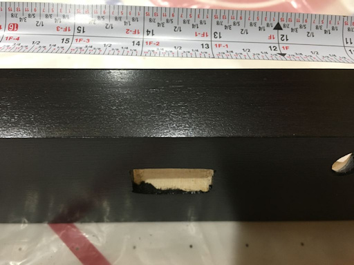
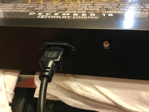
The power into the frame is run through a plug in the center of the bottom portion of the frame. I thought it would look a little strange if the power cord entered the frame off center. The hole for the motion sensor was drilled a few inches off center and will be below most people's field of vision, except for maybe little kids.
Buttons on the top
I decided to install the three arcade buttons in the frame on the top. These are black in color and blend in with the black stain on the frame. I installed the buttons with enough separation so it would be easy to push one without accidentally pushing on one of the others.


Step 4: Neopixel LED and Component Wiring
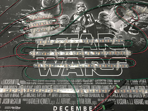
The LED wiring may look a little overwhelming, but since the LEDs are addressable you have a lot less wiring than if the LEDs had to be wired individually. For each string of LEDs you have a positive, a negative and a control wire. With these three wires you can run a large number of LEDs.
I actually started trying to program the LED strips by using one long strip. I ran into problems with trying to run loops on the two different portions of light sabers and other areas of the poster. I decided to make three individual strips that were controlled independently by the Arduino board.
The first strip has the LED lights for Kyle Ren's light saber.
The second strip has the LED lights for Finn's light saber.
The third strip is everything else.
You will see in the pictures that some of the strips are broken up into smaller lengths of LEDs. This is possible by connecting one strip to the next with extension wires soldered between the shorter strips of LEDs. The control wire for each strip needs to run sequentially through all of the strips of LED's.
It is important to run the control wire from start to end of the Neopixel strips in one continuous path. The power wires can be connected to the strips at various points and is good practice if the Neopixel strip is very long. This keeps the current from getting to high through any part of the strip.
You can find an incredible resource for wiring and programming the Neopixels at Adafruit with the Adafruit NeoPixel Überguide.
You need to install a 1000 µF Capacitor, 6.3V or higher at the power connections to the LED strips.
You also need to install a 300 to 500 Ohm resistor between the Arduino data output pin and the input to the first Neopixel in a strip. I used 470 Ohm resistors.
The pushbuttons also need to have a resistor in place between the pushbutton and the ground pin for that pushbutton.


Step 5: Sensors
I had planned to add a few sensors to the poster so it could have some additional functionality.
Photocell
I was going to add a photocell to use for brightness control, but decided not to as I wanted the poster frame to look very clean and without a lot of holes. I thought that by adding a hole with a photocell that it may distract from a clean appearance.
Microphone
I also thought about adding a microphone so it would have a mode where it lights up when it senses sound. I decided against this for the same reason as the photocell.
I thought it would have been a lot of fun to have the poster function as a VU meter for listening to music. This way one light saber could be animated for the left sounds channel and one for the right.
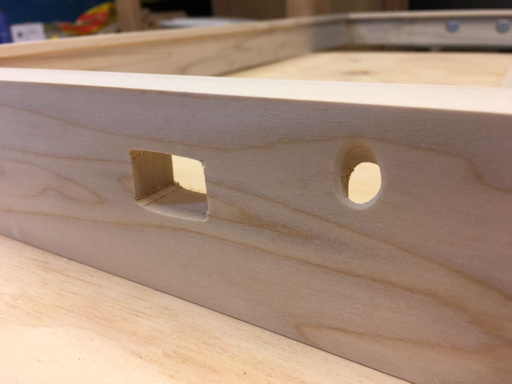
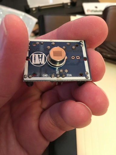
Motion Sensor
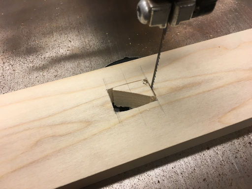
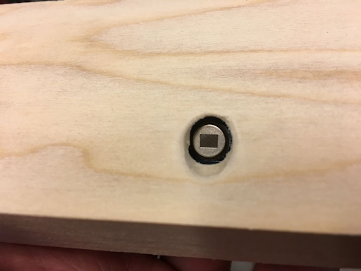
I decided to keep the motion sensor option for the poster so that the poster could be used as a motion sensing night light (an AWESOME one). I drilled a 3/8-inch diameter hole in the bottom of the poster frame for the motion sensor to "look" through. I drilled it at about a 45 degree angle. I actually used a Kreg pocket hole bit to do this as they are extremely sharp and was just the right diameter for the sensor.
I made a couple test holes with this before I actually drilled through the bottom of the poster frame. I didn't want to ruin anything after cutting all of the dovetails for the frame. I drilled the hole by starting the hole perpendicular to the board surface and then slowly angled the drill bit to around 45 degrees. This angle would allow the motion sensor to "see" an area right in front of the poster. Once the hole was drilled I softened the edged of the hole with a round file and some sand paper.
I also used a forstner drill bit to hollow out a small area for the motion sensor. This allowed the area the motion sensor looks through the only be about 1/4-inch thick and also makes a nice recessed area for the sensor. I secured the sensor with ample amounts of hot glue and one small screw through the circuit board.
Step 6: Frame Stain and Finish
I used General Finishes Black Gel Stain to turn the poplar frame nice and black. I ended up applying 2 coats of the gen stain. I didn't notice until after I had added one one coat of the topcoat that a few areas on the front of the frame had some light areas where the gel stain did not cover completely. This was my fault for not looking at the frame closer before I started the topcoat. I decided to leave it this way as I thought it added a little character.
I used General Finishes Arm-R-Seal Oil and Urethane Topcoat with satin finish to seal it up. When I put this on I actually mixed it in a 50:50 ratio with mineral spirits to thin it out so I could wipe it on with a clean cloth.
I applied 5 coats of the topcoat to the frame and was very happy with the way the finish came out. It is extremely smooth and the satin finish looks great. It also dried fairly quick so I could apply a couple coats in one day.


Step 7: Poster Spacers
The poster spacers are the pieces of wood that are between the back of the plastic sheeting and the back piece of wood that has all of the LEDs mounted to it. These serve two purposes:
They hold a consistent spacing between the poster and the LEDs.
They are screwed to the sides of the poster frame and hold the frame to the back piece.
I used some left over pieces of 3/4-inch thick plywood and cut strips 1-inch wide. Since the strips of poplar I added to the front of the frame were 3/8-inch thick I needed the front edge of the spacer pieces to be 3/8-inch wide or less so there wouldn't be the possibility of a shadow around the edges of the poster.
I took the 3/4-inch by 1-inch pieces and cut a corner off if them so the front edge of the spacer was around 3/8-inch wide. I made the cut on the band saw. These pieces don't need to be extremely nice looking since no one will be able to see them when everything is put together.
I pre-drilled some holes in the sides of the spacer pieces and then installed the spacers on the side of the frame. In order to not install the spacers against the plastic too tightly, I used a card from a deck of playing cards between the plastic sheeting and the spacer board. Once the screws were holding the spacer boards against the side of the frame I pulled out the playing card and the plastic sheets was snug, but not pinched by the spacers.


Step 8: Not Enough Room!
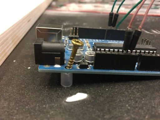
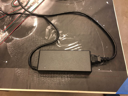
Since I decided to only leave 1-inch of clearance between the plastic holding the poster and the LED lights there really wasn't enough room to mount the Arduino or a power supply. I was originally going to install the Arduino in the frame and have the power supply on the floor. I thought it would look better to have the power supply hidden in the frame. In order to do this I had to cut out some sections of the backer board and hold the power supply in place with some metal strips
I decided to do the same thing with the Arduino since I was worried about having some type of shadow effects inside the frame. I cut out a section of the backer board and then mounted a piece of plywood to the back of the backer board. The Arduino was mounted to this piece of wood.
By mounting the Arduino this way I am able to also access the Arduino board to connect my computer for programming or hit the reset button. This makes is easy to either connect the Arduino to the power supply within the poster frame or connect it to the computer for programming. Both supply 5 volts of power to the board. Just make sure you don't connect them both at the same time. Not sure if that would cause an issue, but I would not recommend it.


Step 9: Cleat Hanging System
I used what is called a "french cleat" system to hang the poster frame on the wall. This is a really easy system to build and use and can hold a lot of weight. It is made by cutting a 45 degree angle on the edge of two boards. One board is mounted on the wall and the other board is mounted on the back of the poster frame. The board on the wall creates a lip that the board on the back of the poster frame matches into. See the pictures as this is much easier to understand with pictures than describe with words.
I made the board on the wall tall enough so that two screws can be driven into a wall stud. The whole poster frame assembly is pretty heavy and I would not plan on mounting this just in drywall. This way the cleat board can be mounted to the wall with the top screw, leveled, and then a bottom screw added. This makes it very easy to get the poster frame mounted plumb the first time and doesn't allow the frame to rotate on the wall.
I ended up drilling 3 columns of 2 holes. I drilled the two holes on the center line of the cleat and then I drilled two more holes one inch away from the center line of the board on both sides. This gives me some flexibility in the future so that if I ever need to mount the poster centered a little left or right of a wall stud.
There is also the option of adding mounting holes to the wall cleat spaced out at 16 inches between holes so that the cleat can be mounted between two separate wall cleats. I'll add these later if I need them.


Step 10: Testing Small Sections of Code
Most of the programming was accomplished by using example bits of code and the NeoPixel library available at Adafruit.com who supplies the LED strips.
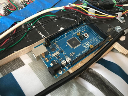
The heavy lifting on this project is done by an Arduino Mega. It controls the addressable LEDs. I started out with an Arduino Uno, but once I started programming I quickly ran out of memory on the Uno card.
Programming
Once you are able to connect to your Arduino board with your computer you will need to install the Adafruit NeoPixel Library.
Click here to go to the Adafruit Uberguide to learn how to install the library.
Multiple Strands
I was going to have one control wire control all of the 172 LEDs. And yes, that is the number of LEDs in the poster frame. Trying to separate out the animations for the two light sabers and all of the other items quickly became an uphill battle so I decided to set up the two light sabers up on their own control lines.
I made an animation loop for the third control wire for all of the items on the poster that are not light sabers.
Since the timing on this routine was going to repeat I decided to have certain items change over a timeline. I created remark lines that designated a certain time period within the timeline. I then added code for the timeline for each time interval. This made it easy to focus on individual parts of the poster. I started with the Star Wars logo and added the animation effects for that. Then I moved on to the title of the movie located between "Star" and "Wars". I worked my way through the rest of the LEDs in order to set up all of the animations. This could have been very time consuming if I was trying to write the code line by line.
Using Excel to generate code
I started writing the code of the color animation sequences and realized it was incredibly hard to keep all of the numbers straight. I realized that I needed to find another way to focus on certain colors for the different parts of the LED strips.
Since the Arduino editor is just a text editor I thought there might be a way to create the code using a timeline and text generated from cells that were pasted together. This worked much better than expected as this made it much easier to work on the LED brightness settings for each of the LEDs. I used the Excel CONCATENATE function to merge cells together into one line of text. The individual columns allowed me to focus on one color of the LEDs at a time without having to try to edit text with the columns not lining up in the Arduino editor. Sometimes a thought can turn into a huge time saver. I don't know if I would have been able to program everything in this project without doing it this way as the code in the Arduino editor would be very hard to follow.
The process for exporting code to the Arduino editor involved the following:
Edit cells in the spreadsheet.
Copy the rows of the cells I wanted to copy to the Arduino editor.
Create a new Excel sheet and paste the contents into the sheet "as values."
Delete all of the other columns except the time column and the code column.
Use the Data Sort function to sort the entire sheet by column "A" (time) in ascending value and then column "B" (code) in ascending value.
Copy the column with the code lines into the Arduino editor.
The programming I came up with to make the animation effects for the poster involves updating the LED values and then updating those once every 50 milliseconds which is the value for the duration variable DUR. This variable can be changed in the code to speed up or slow down the animation effects.
This creates a lot of code fast. When I exported everything the first time I realized that the Arduino Uno that I started with would not have enough memory for the animations effects and duration that I wanted. I ended up switching to an Arduino Mega and also put sections of the animation effects into loops that could be reused. This made everything work out great, but meant extra time to swap the boards and also create the loops.
A lot of the testing was done by testing individual sections of only one area. This allowed me to make quick changes. For instance, I could work on the animation of Finn's light saber, export the code, check to see if I liked it, adjust and try it again.
Once I had the different LED sections looking the way I wanted them to, I just needed to assign that section a time sequence.
I assigned different sections in the time line to different routines that could be called when needed. I guess you could call them building blocks for the different animations.
Once I exported all of the sections I placed different sections in different routines that I could call. That way the animation effects just turned out to be calling the animation parts in the order I wanted to display them in.


Step 11: Modes of Operation and Button Controls
I added three black arcade pushbuttons with momentary switches to the top of the poster frame. These allow the user to control the Mode of operation, the brightness level of the LEDs, and the duration of time the display is on when activated by the motion trigger.
Left Mode Button
The left arcade button cycles through the 8 different Modes of the display:
Motion Color - Motion activated color display.
On Color - Constant color display.
Motion White - Motion activated white back lighting.
On White - Constant white back lighting.
Motion Sabers- Motion activated light sabers only.
On Sabers - Constant light sabers only.
Motion Rainbow - Motion activated light saber rainbow effect.
On Rainbow - Constant light saber rainbow effect.
Changing Modes on the poster is signaled by all of the LEDs in the poster flashing in white the same number of times as the mode you are changing to. For example, if you hit the left button and the poster flashes 1 time then you have just entered Mode 1 for a motion activated color display. If you hit the button again then you will enter Mode 2 for a constant color display.
Middle Brightness Button
The middle arcade button cycles through the brightness settings of the LEDs moving in increasing brightness levels to maximum brightness levels and then starts back at the minimum brightness level. When the middle button is pressed, Finn's light saber lights up red for a short time at the new brightness level and then the display continues with the display mode it was in before you pressed the button. I set variables that have the minimum brightness level, maximum brightness level, and step for brightness changes so I could change the settings later without too much trouble.
Right Duration Button - Press to control the duration of the animation sequence.
The right arcade button cycles through the duration of the display when the poster is in a motion activated Mode. Pressing the button changes the duration from minimum to maximum and then starts back at the minimum duration setting. When the right button is pressed, a portion of Finn's light saber lights up red for a short time based on the duration setting. The minimum duration setting value is 10. The code takes this value and divides it by 5 to display only 2 LEDs lit up at the current brightness setting. The longer the duration - the longer the portion of Finn's light saber that lights up. I set variables that have the minimum duration length, maximum duration length, and step for duration changes so I could change the settings later.


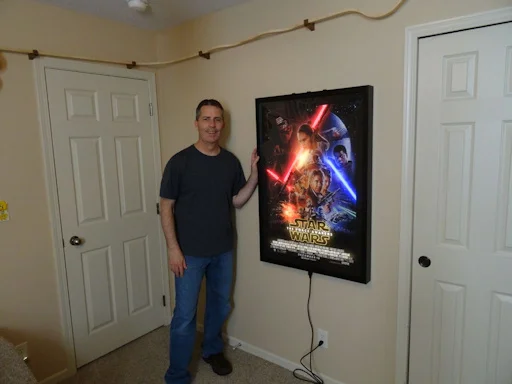
Step 12: Completed Poster
I am very happy with the way the poster turned out. I think it ended up being a more than challenging project for for my first Arduino project. There were multiplied times close to the completion of the project that I thought I may not be bale to make thing work like I planned. If you didn't see this earlier, I had to change from an Arduino Uno to an Arduino Mega just for the memory available in the Mega board.