How to Build a Chain Clock
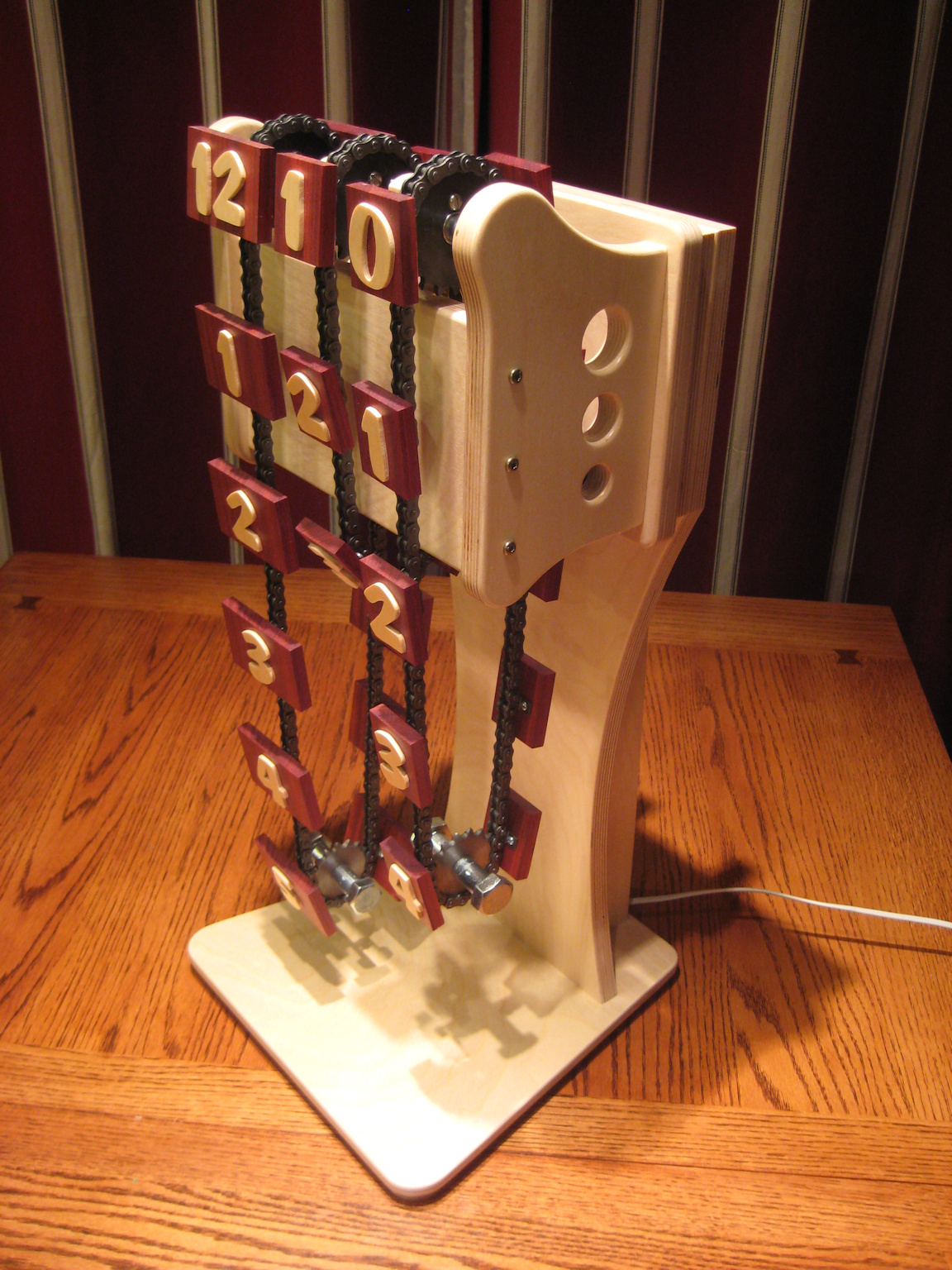
This will show you how I made awhat I call a Chain Clock. This is a clock where all of the numbers that show the time are suspended from chains. The chains rotate in order to change the time.
This clock is something I have been thinking about building for several years. I was brainstorming on different types of clocks that could be built using mechanical parts with some type of motion involved. I come up with several ideas, but this is the one I wanted to build first. I haven't been able to find anything else like it. With all of the different parts involved it was a big challenge not having something to look at as an example.
The video below shows the motion of the clock through several minute changes. There is also a clip that have been sped up 10 times normal speed. The clock is a lot of fun to watch as the time changes.

Step 1: Parts, Materials, and Tools Needed
A lot of the parts I used to build this clock were items that I already had or had left over from other projects. I recommend that you customize this or other projects to use up some of your existing materials. For me it's a great feeling to use up left over materials instead of storing them for years or throwing them away. Also, it saves you money and you make room for the next big project.
MATERIALS
3 gearmotors from ServoCity - 12 volt dc at 4 rpm
3 motor mounts from ServoCity
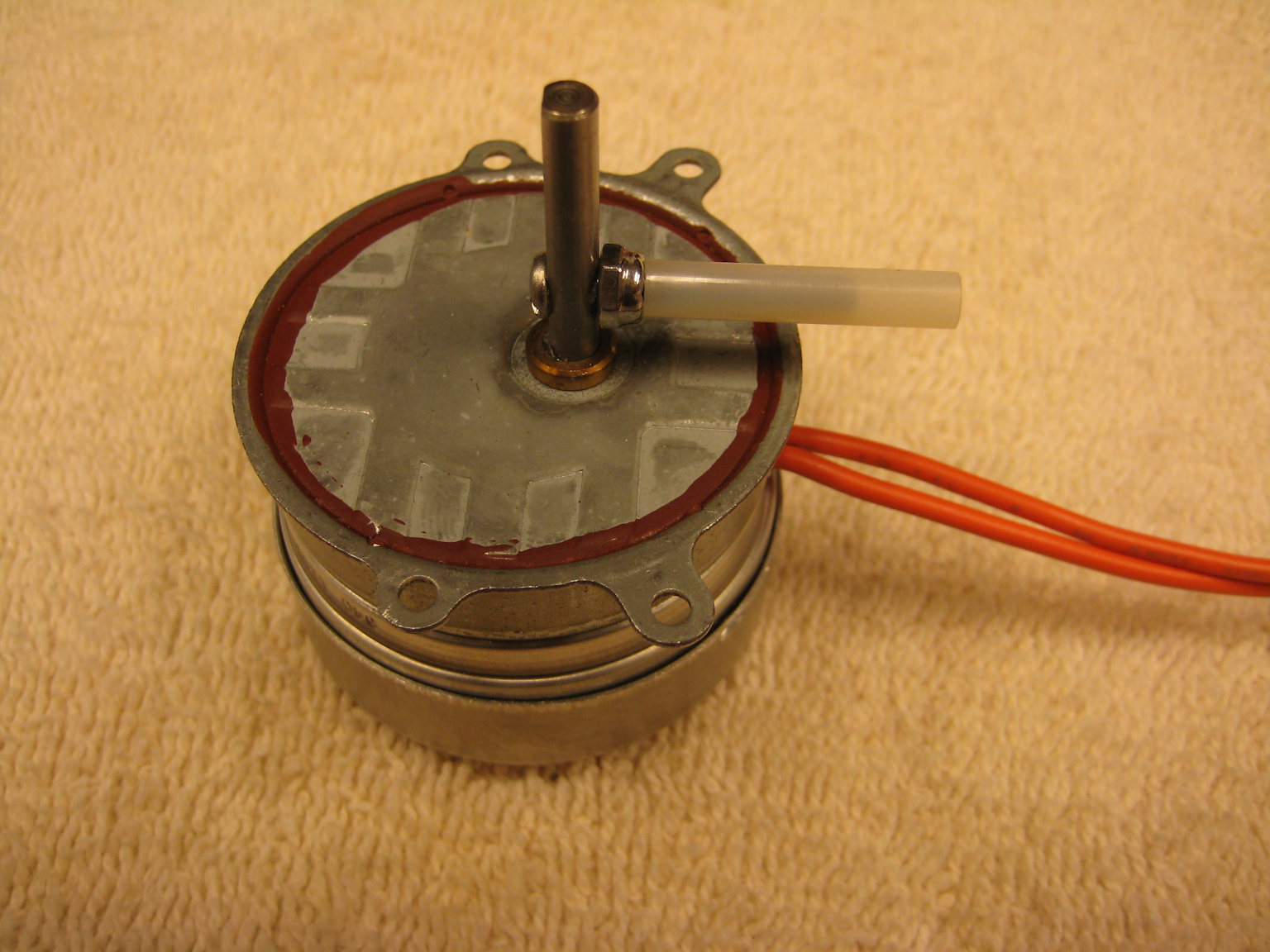
1 - 1rpm ac synchronous motor
baltic birch plywood for supports and for numbers
bloodwood for the number plates 9 nice contrast)
screws - multiple types and sizes
electrical cord for AC power
20 gauge stranded electric wire for 12 volt dc wiring
pushbutton switches from Radio Shack - normally open
AC transformer for the 3 dc gearmotors - part number 273-1365A
bridge rectifier from Radio Shack to convert transformer voltage from ac to dc power- part number 276-1173
5/8 inch outer diameter by 1/4 inch inner diameter ball bearings
1/4" steel rod
stop collars
bolts and machine screws
#35 sprockets - need 3 with 20 teeth with a 5/8 inch diameter
- need 3 with 16 teeth with 1/2 inch diameter bore (no hub)
- need 3 with 12 teeth with 1/2 inch diameter bore
CHAIN
#35 roller chain -McMaster - (404) 629-6500. http://www.mcmaster.com/ part# 6261K172
Chain connecting link -McMaster - (404) 629-6500. http://www.mcmaster.com/ part# 7321K3
All wood pieces were finished with water based polycrylic.
Tools
The tools I used on the project were as follows:
1. Table saw
2. Band saw
3. Oscillating spindle and belt sander
4. Cordless drill
5. Drill press
6. Random orbit sander
7. Router
8. Router table
9. scroll saw (for cutting out the numbers).
10. Hacksaw or cutoff saw
11. Sanding block with sandpaper
12. Screwdrivers and wrenches
13. Soldering iron
14. Wire cutters
Not all of the tools in this list are required, but will make the construction much easier.
NOTE: If you plan on using any tool for a project please make sure you are familiar with the tool and all of the dangers associated with it. If you are not familiar with a tool then you should ask someone who is to show you the proper way to use it. A lot of communities have classes at local colleges on the proper use of tools and machinery. There are also local woodworking clubs that offer classes at very reasonable rates for beginners. I highly recommend using these resources for your safety and for the most efficient use of the tool.
SAFETY FIRST
Always wear eye and hearing protection.
Always work safe with the proper safety equipment and guards on your tools.


Step 2: How It Works
This clock is made up of one synchronous motor and three small 12 volt dc gear motors that actually drive the chains.
The synchronous motor is what keeps the timing of the clock. The motor shaft makes one revolution every minute. Once every revolution the shaft closes the contact between two brass strips. These strips allow 12 volt dc to run the first dc gear motor that controls the chain with the "minutes" After this gear motor starts spinning it turns the chain and closes another set of brass strips that keep the gear motor running until the "minutes" are in the correct position.
When the "minutes" chain has moved to the point where the zero is coming into the correct position then contacts are closed for a brief time for the second gear motor that runs the "ten minute" chain. This operates the same way as the "minutes". Each chain triggers the gear motor that runs the next chain.
So the "minutes" chain runs once every minute, the "ten minute" chain runs once every ten minutes, and the "hour" chain runs once every hour.
Watch the video in step 1 to see see how it looks when it runs.
Step 3: Wood Supports
The clock is supported on four main pieces of wood. Those four pieces are hung on the wall using a wooden cleat system. The pictures and video of the clock currently show it on a temporary stand. I plan on making a nicer stand in case I would want to locate the clock on a table instead of the wall.
The are four main wood supports for the clock. We will call these the back, front and two sides.
The back piece supports the two side pieces and has a cleat on the back for hanging the clock on a wall or stand.
The two side pieces support the front. The front holds the three gear motors, the timing motor, a transformer, and the quarter inch diameter shaft, which supports the sprockets and chain assemblies.
The wood that I used for the main pieces was 3/4 inch baltic birch ply. I had these pieces left over from other projects and love using it due to its stability. It also rarely has voids like a lot of other ply material.
If someone is interested, I can provide the dimensions for the wood pieces in this clock. I think I can get you PDF files of the autocad file so if you print them out at 100% scale then you can use spray adhesive and attach them to pieces of wood. That is how I cut out the side pieces and located the screw holes on the side pieces.


Step 4: Metal Support Rod
The metal support rod is a 1/4 inch diameter steel rod. The metal support rod holds the sprockets that supports the three chains. Each #35 roller chain sprocket also has a 3/4 inch thick wood circle with flats attached to one side. We will call these "flattened circles" for my lack of a better name. The flattened circles act as a switch for the gear motor that drives that chain. Make sure you cut the metal rod the exact length of the distance between the wood sides plus the depth of the holes you drilled in them. This will keep the metal rod from sliding side to side in those holes.
The sprockets and the wood circles are attached to each other by two #8 by 2-inch long machine screws with nyloc nuts. Drill the holes through the sprockets and the flattened circles slightly larger than the diameter of the machine screw. This allows a little adjustment to them if you need to true them up.
Add a shielded roller bearing on one end of this assembly to the metal sprocket and one to the flattened circle. I used a little epoxy on the outside edges of the metal sprocket and the flattened circle to hold the bearings in place. Don't used too much or you risk getting epoxy on the inner portion of the bearing.
These metal sprocket and flattened circle assemblies are held in place by 1/4 inch inner diameter shaft stop collars. These make it easy to adjust the spacing of the chains.
One thing to note when buying a steel rod for the support rod. There can be a lot of variation in the actual diameter of the steel rods. I recommend taking a micrometer to the store where you are buying the rod so you can make sure the diameter of the road is just at 0.25 inches. A slightly smaller diameter for the rod may even be better. The problem is that the bearings you will use for the rod will be very close to 0.25 inches in diameter and if the rod you buy has a larger diameter, even by a couple thousandths, then you are never going to get the bearings over the rod.

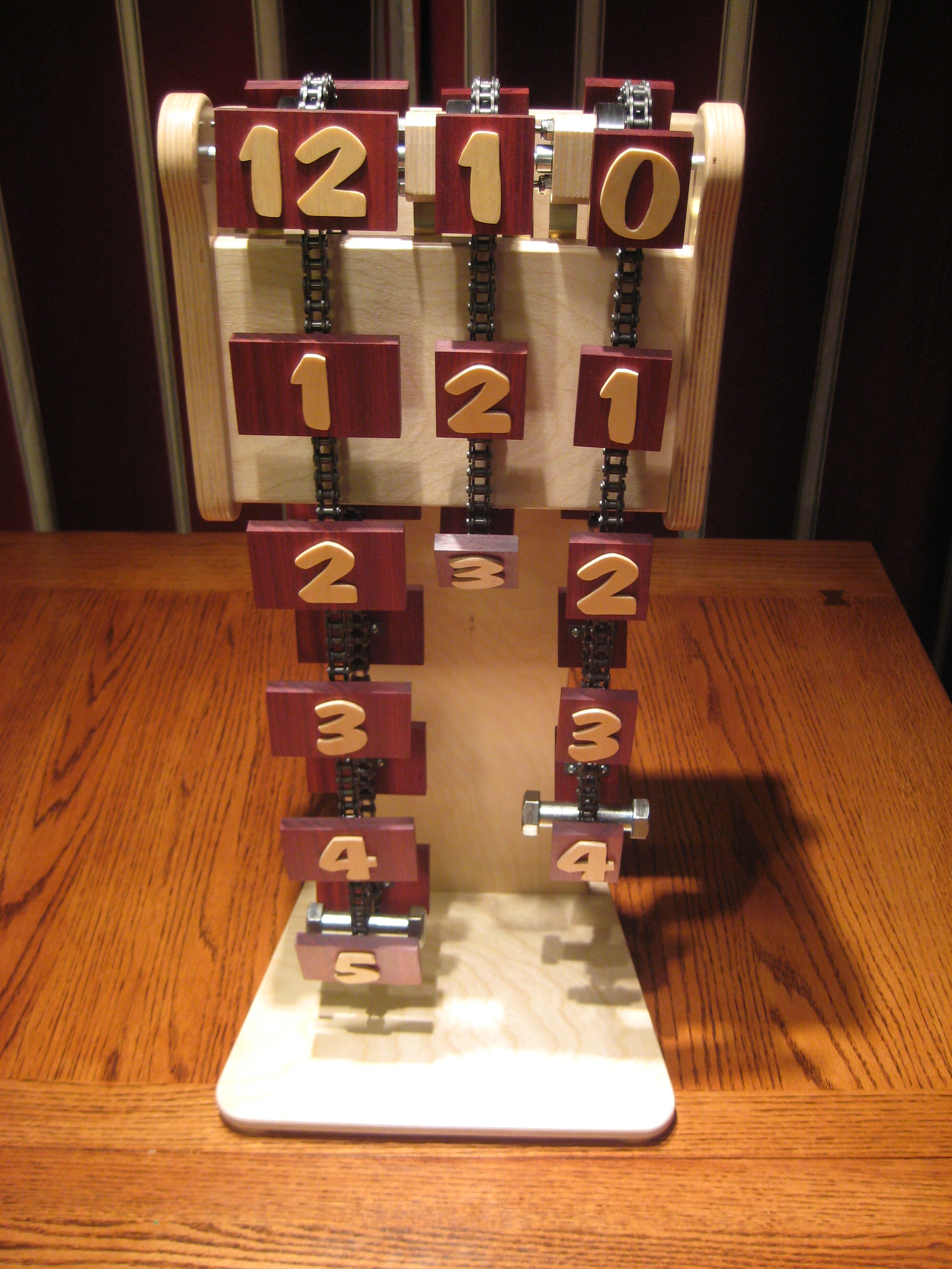
Step 5: Number Plates
The number plates for the clock are made from bloodwood. This wood was a great contrast to the numbers which are 1/8" baltic birch ply as well. I also like the bloodwood for the rich color it has and the contrast to the light birch numbers.
I used a thickness planer to get the wood to a uniform thickness.
Next I cut the pieces to size on a table saw using stop blocks to get uniform sizes for all of the rectangles.
I recommend drilling all of the holes in the back of the number plates using a drill press with stops in order to get all of the holes drilled in the plates in exactly the same locations.
The number plate dimensions are as follows:
The "hours" plates are 2-15/16 inches wide by 1-7/8 inches tall by 5/16 inches thick.
The "minutes" and "ten minute"plates are 2-15/16 inches wide by 1-7/8 inches tall by 5/16 inches thick.
I think a great option on the number plates would be to use a laser cutter to burn the numbers into the pieces of wood.


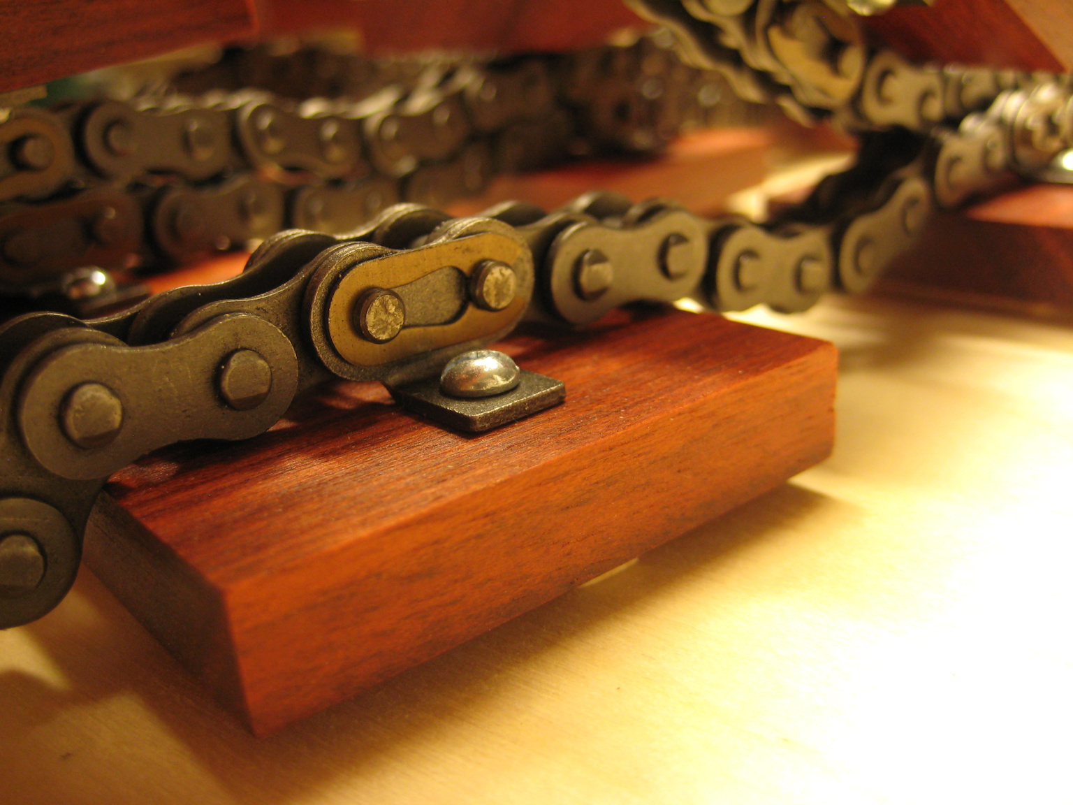
Step 6: Chain Assembly
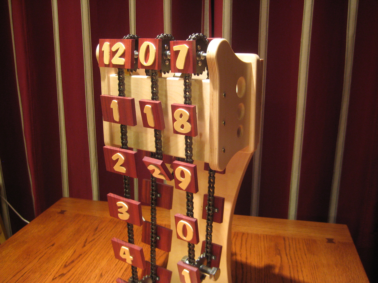
The chain assemblies are fairly straight forward. Each of the three chains are made up up short sections of chain with tabbed connecting links holding them together. The wood rectangles with the time numbers are then screwed to the tabs on the connecting links. The tabbed connecting links were purchased through McMaster.
While some might think the connecting links are a little pricey, I have not been able to find a better or cleaner way to connect the wood to the chain.
In my opinion, the spacing between the tabbed connecting links really needs to be one half of the number of teeth on the sprockets you are using. This is key with the switches for the rotation of the sprockets in the way that each sprocket only rotates 180 degrees to move the next number into position.

Step 7: Spacing of the Chains
The horizontal spacing between the chains is really a matter of preference and of spacing for the components. I would have liked to set the "minute" and "ten minute" chains closer together, but there was a conflict with one of the motors.
I originally set the size of the wood plates the numbers are on based on the size of the numbers. Then I set the spacing between the number plates based on how they all looked together. Then I had to readjust the spacing a little based on clearances. It really comes down to a personal preference and the look you are going for.

Step 8: Chain Weights
I made a weighted sprocket for the bottom of each chain using a hubless sprocket and some large bolts. The bolts have the threaded sections cut off. Then a hole is drilled and tapped to take a machine screw. This way the sprocket can be centered between the two bolt section.
You will need to add a spacer to the sprocket that has an outside diameter that is the same as the sprocket and an inside diameter that is the same as the machine screw.
This weight is important in keeping the number plates hanging on the chain vertical.
I added a little dab of epoxy on the the pieces before a put them together just to keep the pieces from coming apart.


Step 9: Motors to Run the Three Chains
The gear motors for the project were from from ServoCity. They operate on 3 volts to 12 volts dc. I ran them at 12 volts dc for the speed of rotation I was looking for, but these gave me the option to run at a slower speed if necessary.
The motors are also somewhat quiet when operating. I thought this was an important aspect of the clock as I wanted to keep things as quiet as possible.
The sprockets for these motors have 1/2 inch diameter bores but the motors have 6mm (metric) shaft diameters. In order to make up the difference I used 3/4 inch long sections of 1/2 inch diameter nylon rod and then drilled a 6mm diameter hole for the motor shaft. Then I set a #4 by 1 inch long machine screw through a hole that I drilled though the motor shaft.

Step 10: Motor Mounting Brackets
The motor brackets were off the shelf brackets that I modified slightly for my needs to fit within the back of the clock.

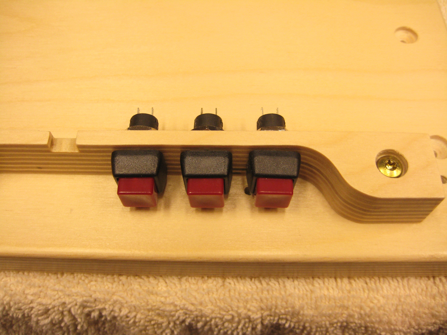
Step 11: Switches for the Motors
The switches for the motors are made from brass strips. These are easily shaped as needed and are very quiet in operation. I was going to use some lever switches with rollers on them, but decided they were too noisy as they clicked on and off.
The brass strips are easily flexible and can be shaped to what you need. The flat spots on the wood circles don't touch the brass strips until the motor starts moving the chain. The chain rotates the wood circle and then the round parts of the circle push the two brass strips together to make contact. The motor keep running until the flat spot on the other side of the circle becomes parallel to the brass strips. The contact between the brass strips stops and the motor stops.
The flattened circles are held to the #35 sprockets with #8 - 32tpi x 2 inch long machine screws located opposite each other.


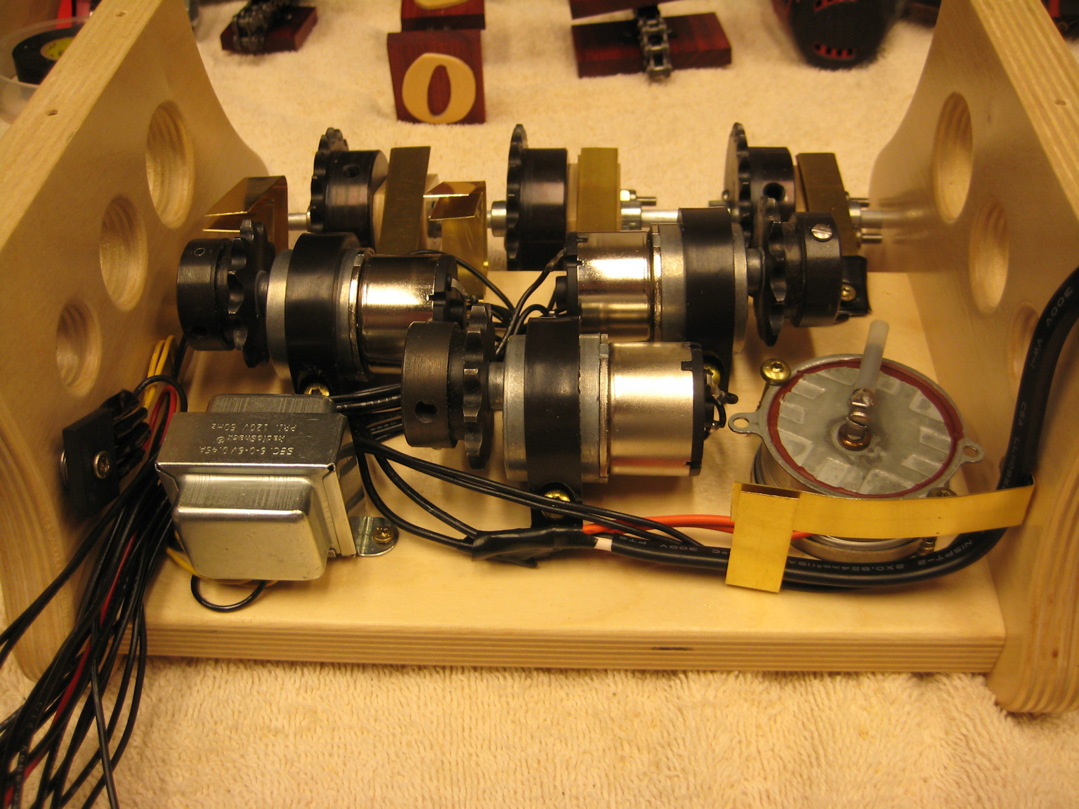
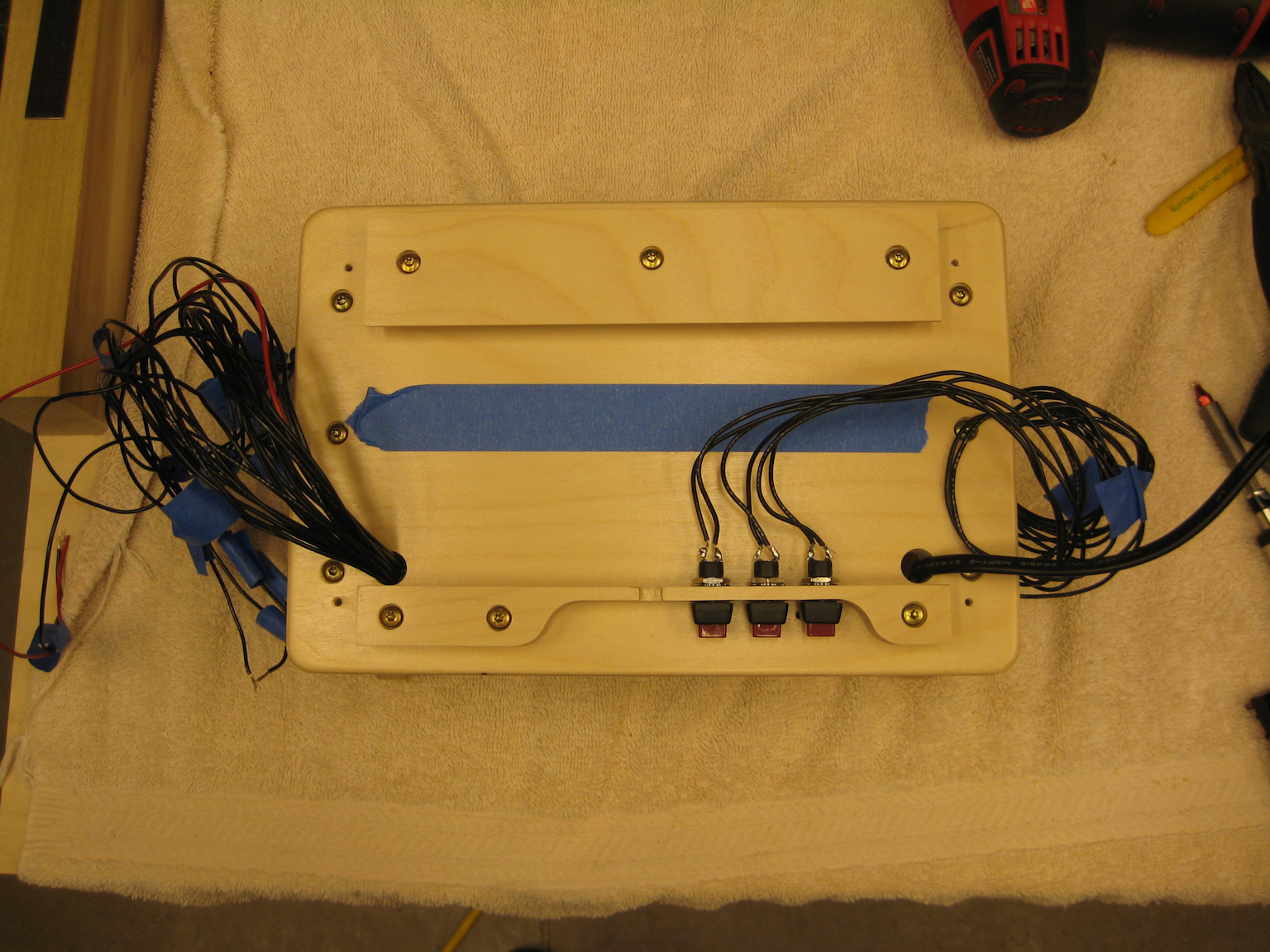
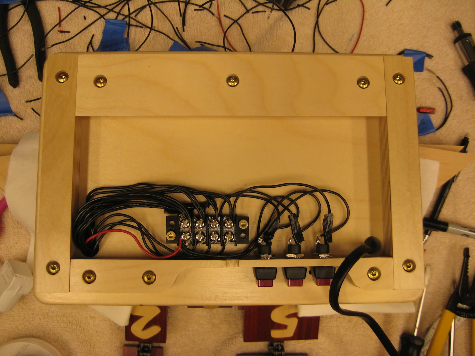
Step 12: Wiring and Switches
Here are some pictures of the wiring and the switches being installed.


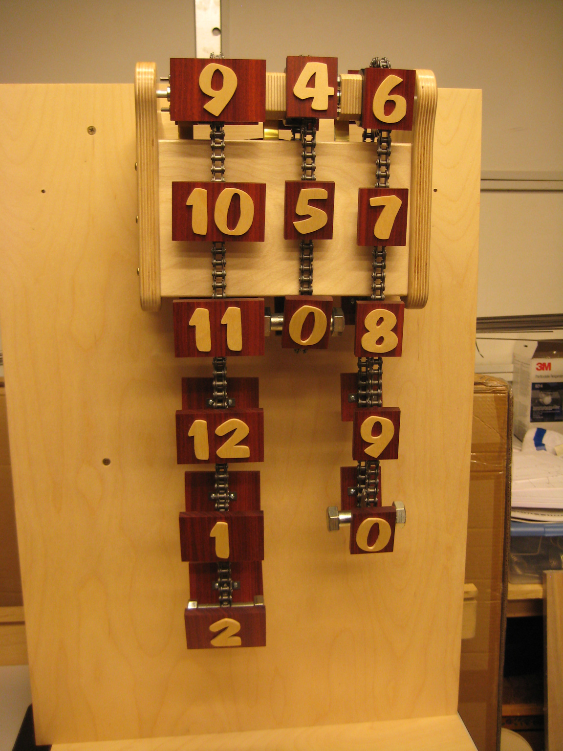
Step 13: Completed Clock
Here are some pictures and video of the completed clock. Please let me know if you have any questions.