Adjustable Width Tool Charging Station
Click here if you want detailed plans and a cut list to build your own.
Click here to subscribe to my YouTube channel.
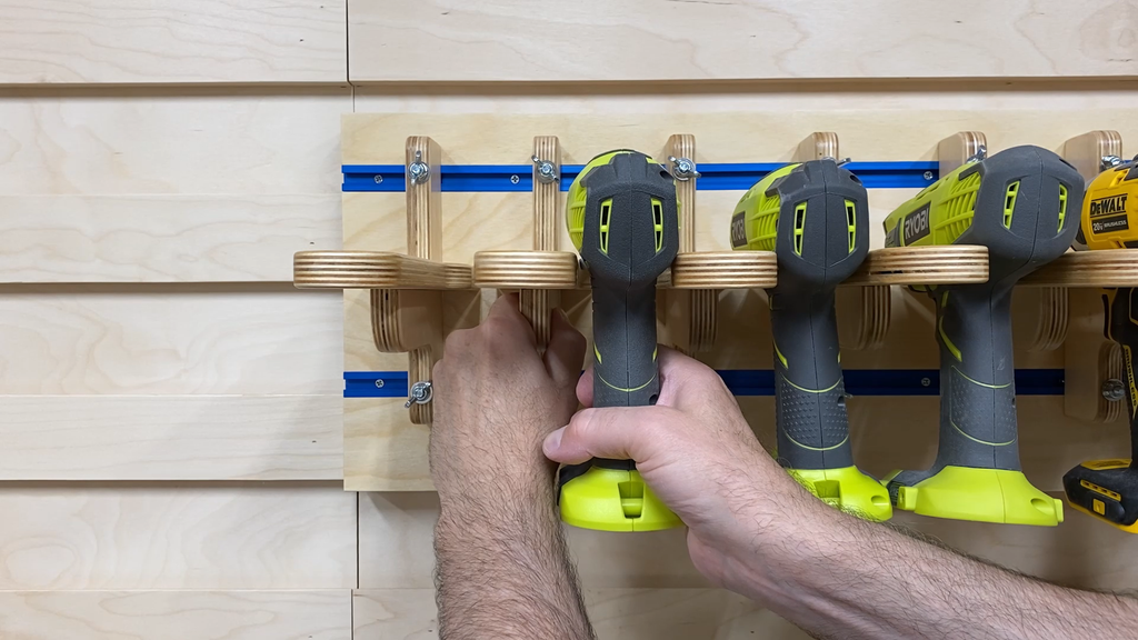
I've been wanting to build a tool charging station for a long time now, but there was always something that bothered me. Once you build the hangers for the tools if you end up replacing a tool and it has a different width or you want to change the layout of the tools, then you have to adjust the hangers and maybe even cut new ones to match the tools. I decided to make a tool charging station where the width could be adjusted easily as needed.
I also wanted to make the tool hanger expandable in case someone wanted to make more storage later. I'll explain more about that later in the project.
This tool charging station was built to hang on a french cleat wall, but can easily just be attached to a wall with screws or with individual cleats.

Step 1: Materials and Tools
Materials
WOOD
3/4" baltic birch plywood - 1 sheet of 3/4" x 60" x 60" or 2 pieces 3/4” x 30" x 60"
3/8" baltic birch plywood - 1 sheet of 3/8" x 30" x 60"
HARDWARE AND FASTENERS
28 - Kreg pockethole screws - for soft wood or plywood - https://amzn.to/2DMSMxh
2 - Kreg KMS7509 4-Feet 48-Inch Mini Trak - https://amzn.to/30XQx3o
8 - #6 x 1-1/4" long flat head wood screws - https://amzn.to/2NXBcYP
8 - #6 x 3/4" long flat head wood screws - https://amzn.to/2ZGeHgv
9 - #8 x 1-5/8" Long general purpose wood screws
9 - #8 x 1-1/4" Long general purpose wood screws
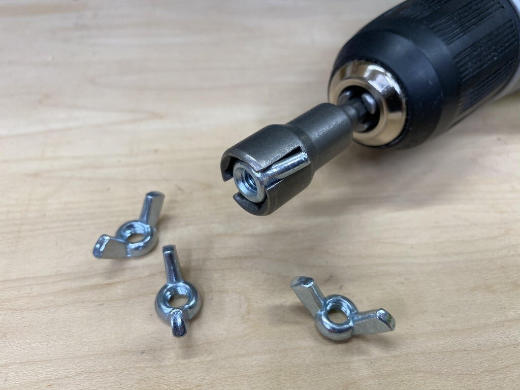
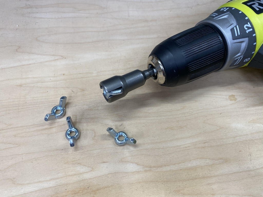
16 - Full Thread Hex Tap Bolts, 1/4-20 x 2-1/2, (100 Pack) - https://amzn.to/3fxpakG
16 - 1/4" Wing Nut 180249 Wing Nuts - https://amzn.to/3fB3PH8
16 - 1/4"-20 Stainless Hex Nut (100 Pack) If you don't want to use wing nuts then you can just use - https://amzn.to/3dam1FP
16 - Stainless 1/4-Inch Split Lock Washer, 100-Pack - https://amzn.to/2V0dKxY
16 - 1/4" Stainless Flat Washer, 5/8" Outside Diameter (100 Pack) - https://amzn.to/30RbwF4
1 - 24” Under Cabinet Lighting 4000K - https://amzn.to/3dcvgFt
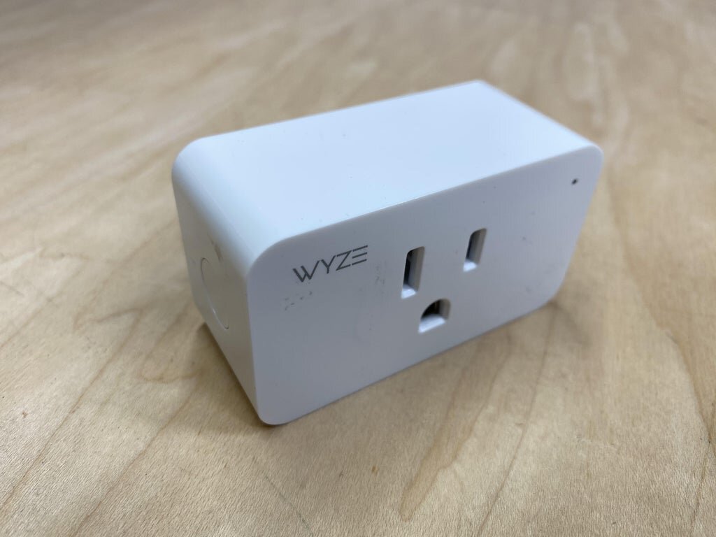
1 - Wyze Plug, Compact WiFi Smart Plug - https://amzn.to/2Yeb69V
1 - Tripp Lite 7 Outlet (6 Individually Controlled) Surge Protector Power Strip - https://amzn.to/2BoA1yQ
Tools - The tools I used on the project were as follows:
Kreg K4 Pockethole Jig - https://amzn.to/3hLmF0i
Saw Stop table saw - https://amzn.to/3a8znCE
Ridgid oscillating spindle and belt sander - https://amzn.to/3kseUh5
Dewalt 20 Volt Cordless drill - https://amzn.to/3aflH9a
Drill press
2-1/2" Hole Drill Bit (or similar size) - Hole needed if you want to run electrical cords into the charging box
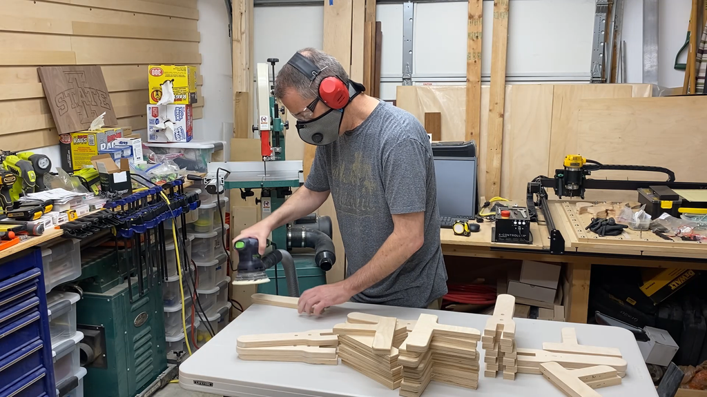
Random orbit sander
Sanding paper
Screwdrivers
Shop vac
NOTE: As an Amazon Associate I earn from qualifying purchases.
NOTE: If you plan on using any tool for a project please make sure you are familiar with the tool and all of the dangers associated with it. If you are not familiar with a tool then you should ask someone who is to show you the proper way to use it. A lot of communities have classes at local colleges on the proper use of tools and machinery. There are also local woodworking clubs that offer classes at very reasonable rates for beginners. I highly recommend using these resources for your safety and for the most efficient use of the tool.
SAFETY FIRST
Always wear eye and hearing protection.
Always work safe with the proper safety equipment and guards on your tools.
Note: As an Amazon Associate I earn from qualifying purchases.


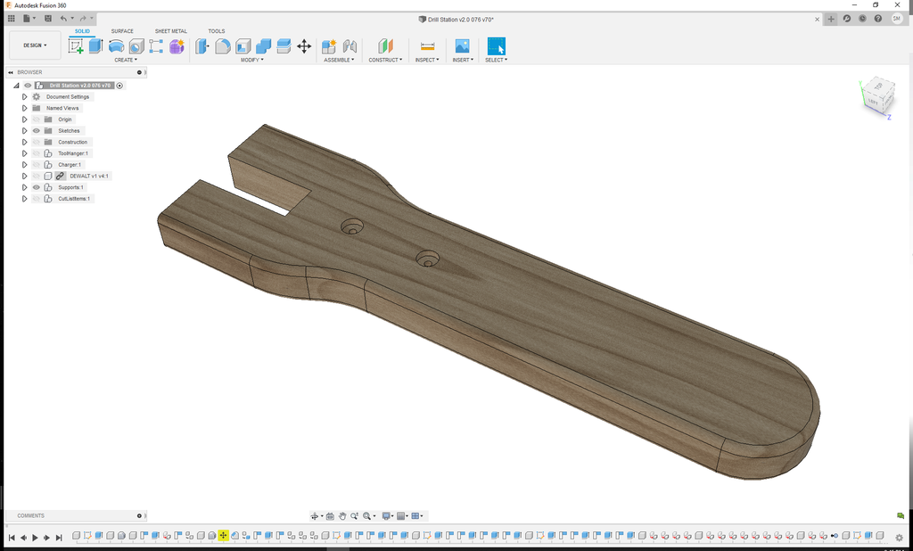
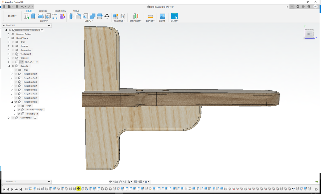
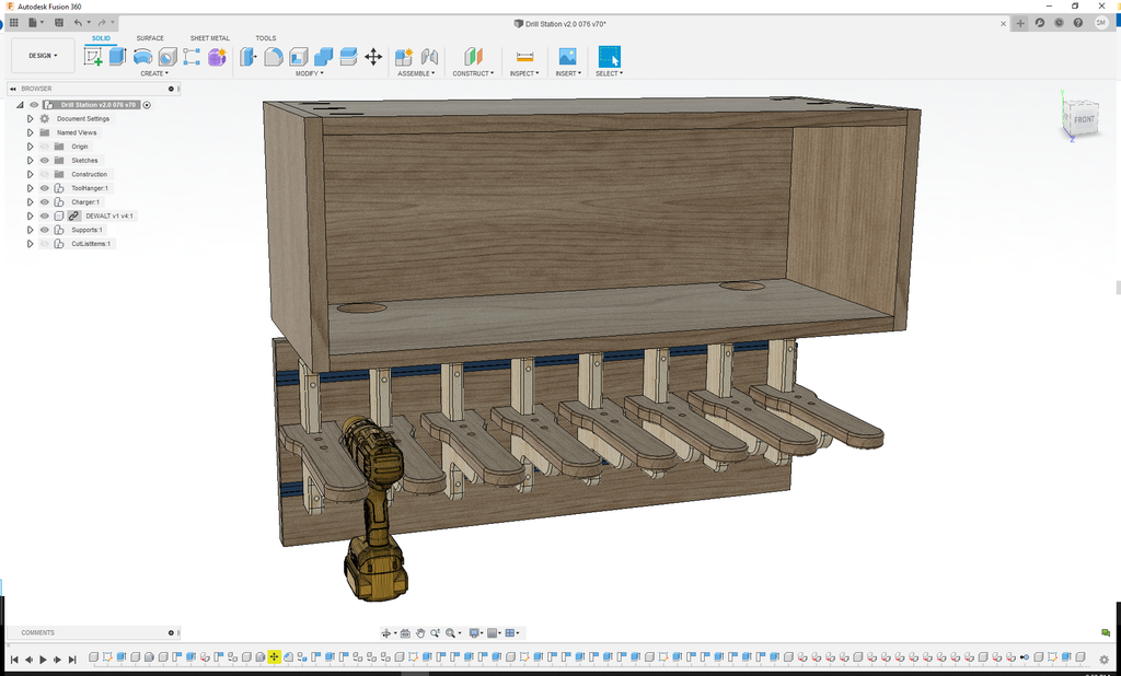
Step 2: Fusion 360 Design
I used Fusion 360 software to design the entire Tool Charging Station before I cut out any pieces.
The tool charging station is made up of two main components.
1. The Tool Hanger - adjustable width tool support.
2. The Tool Charger - The box above the tools with chargers and batteries
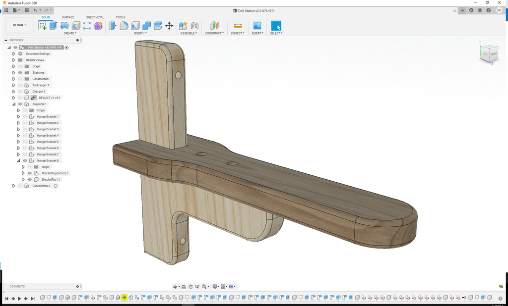
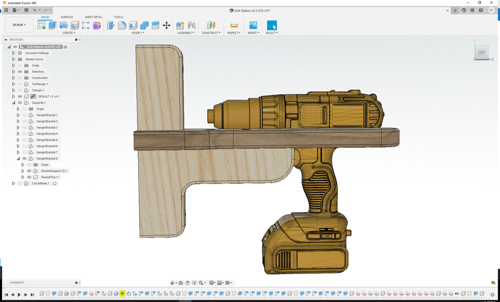
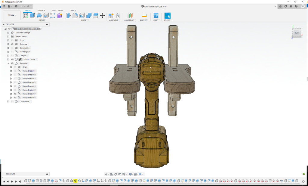
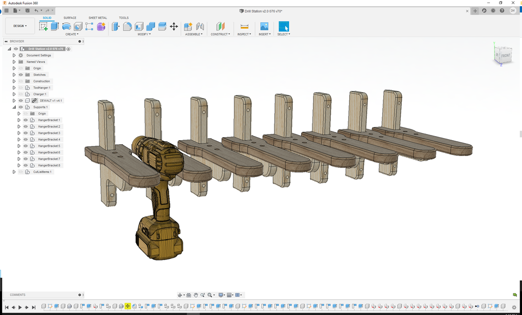
Tool Hanger
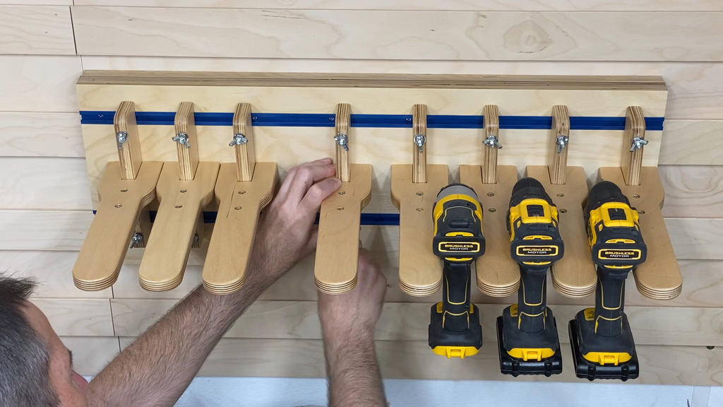
As I mentioned earlier, I wanted the charging station to be easily adjustable. I also wanted to use easy to find parts for it's construction.
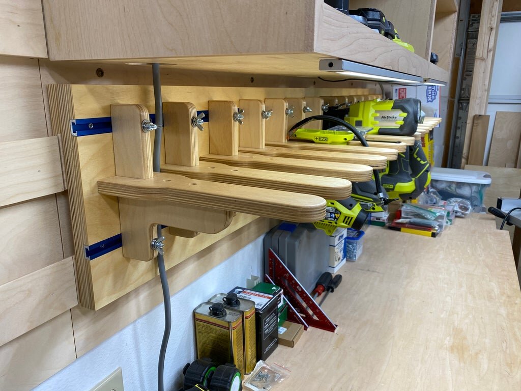
The design of the holders came mostly out of functionality. I wanted a shape that was easy to reproduce, made with easy to find parts, was strong enough for most tools, and looked nice.
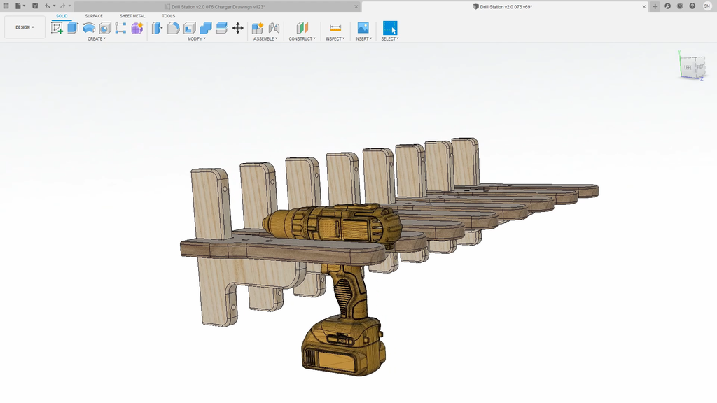
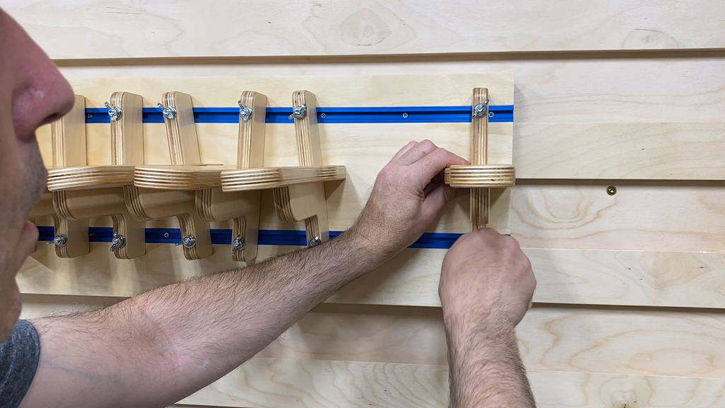
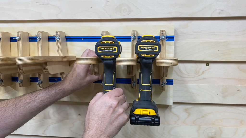
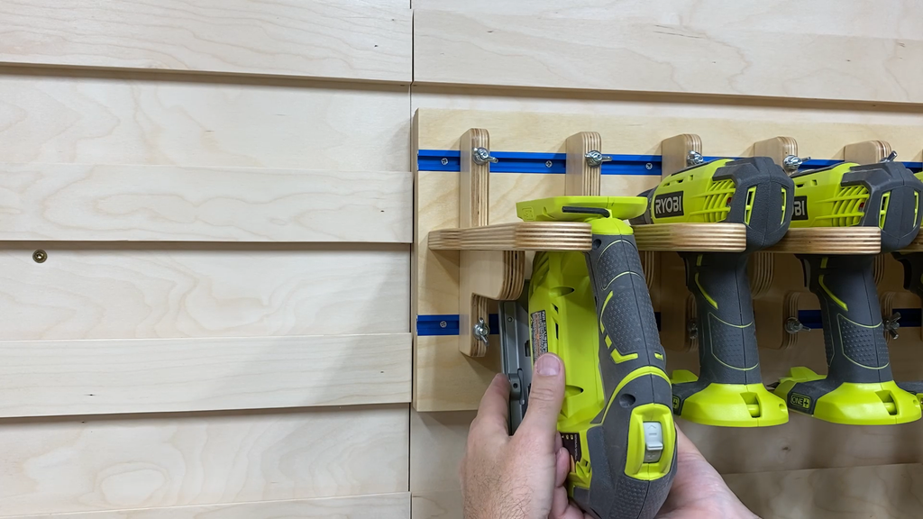
The holders needed to be small enough to not waste space and strong enough to hold up some heavy tools. The shape I came up with makes it easy to put tools away or get them out. It also creates a very sturdy holder for the tools.
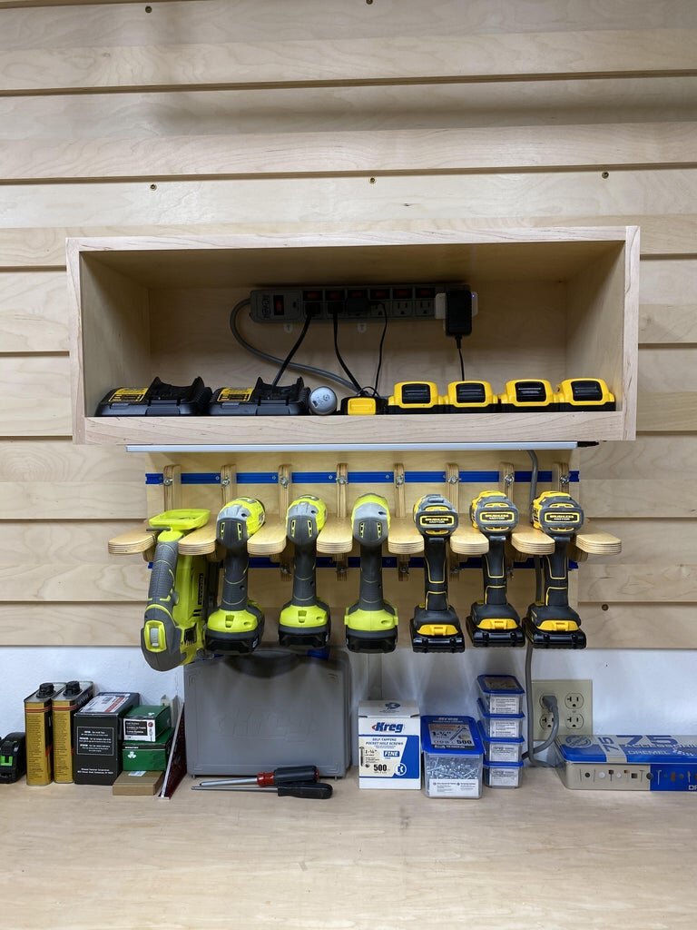
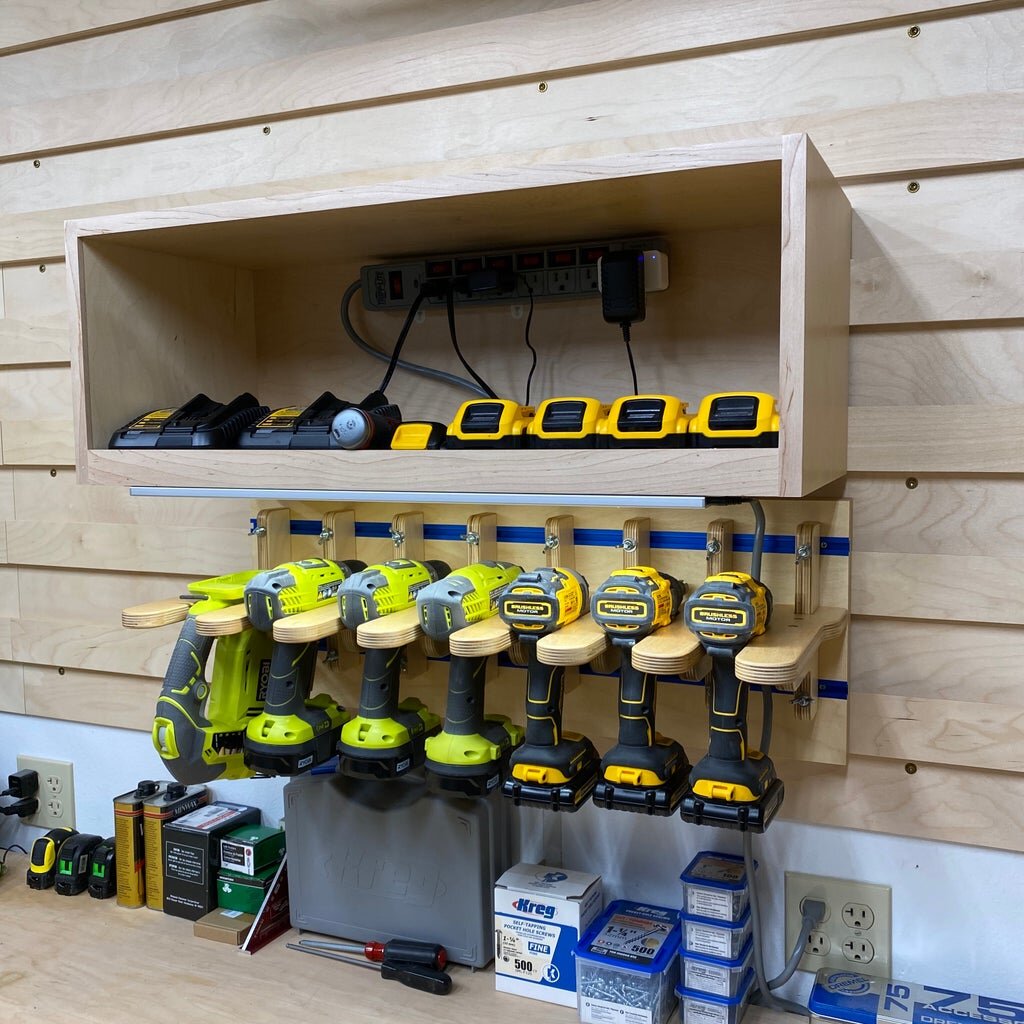
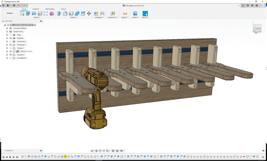
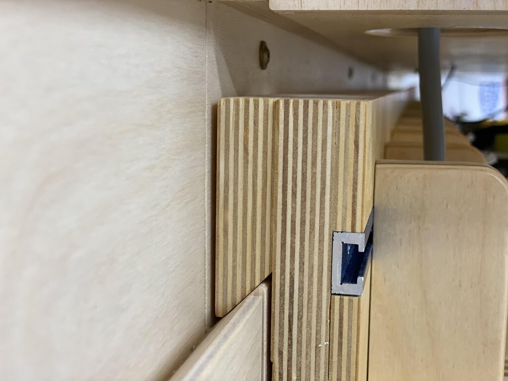
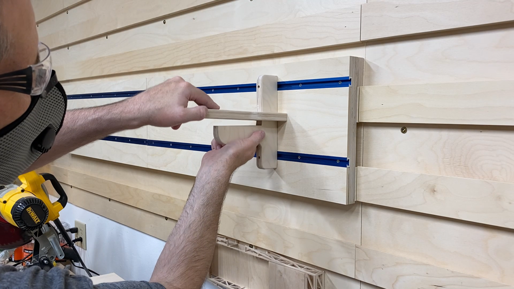
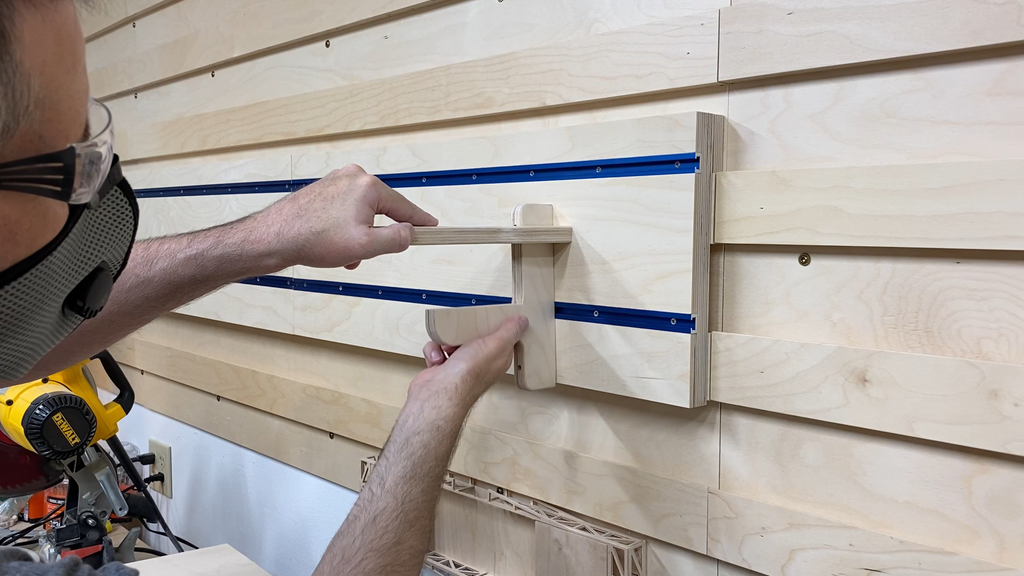
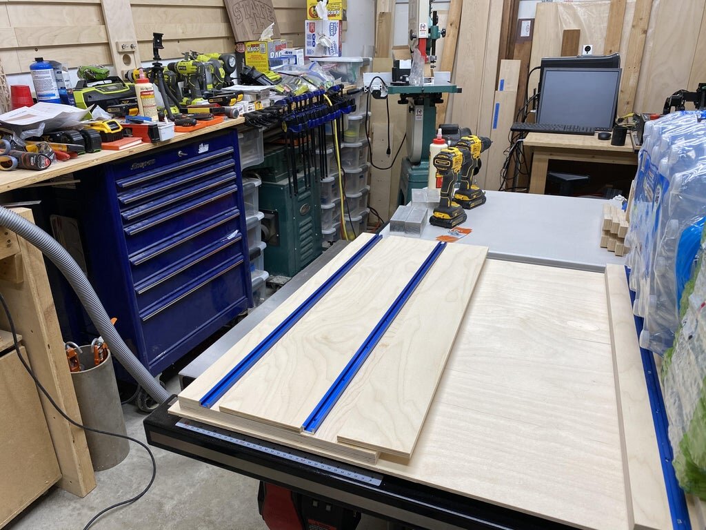
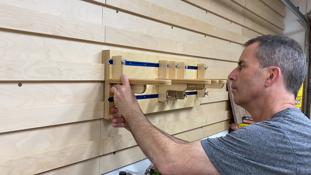
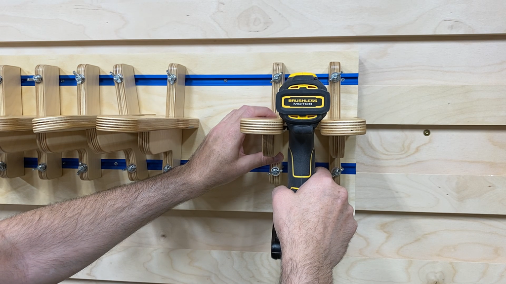
The tool holders slide on parallel pieces of Kreg brand Mini Trak. This is the blue aluminum track that you see in the pictures.
Tool Charger
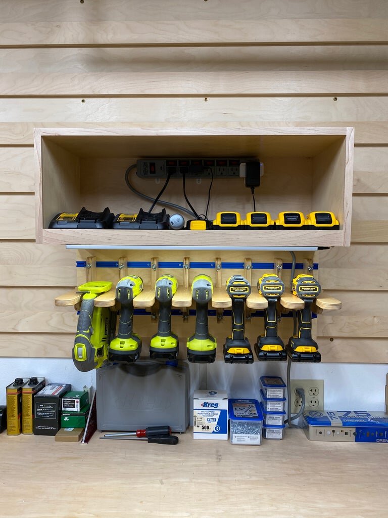
The charging station is little more than a box with enough room to to hold chargers and batteries for the tools. I also wanted to have room for a power outlet strip so there would be a small number of power cords running out of the box to a wall outlet.
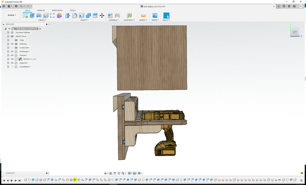
I started the design of the Tool Hanger by sizing the top plate that the tools actually rest on. I wanted to make sure they were wide enough to have lateral stability and narrow enough to not wast space.
Next I added the bottom support for the tool holder. This was designed to have a 6" spacing between the top and bottom bolts that slide in the Kreg Mini Trak.
Then I added the back support for the tool holders. The main idea here was that the average size tools would fit without wasted space above the top of the back support and I wanted it to hang on the wall with a french cleat system.
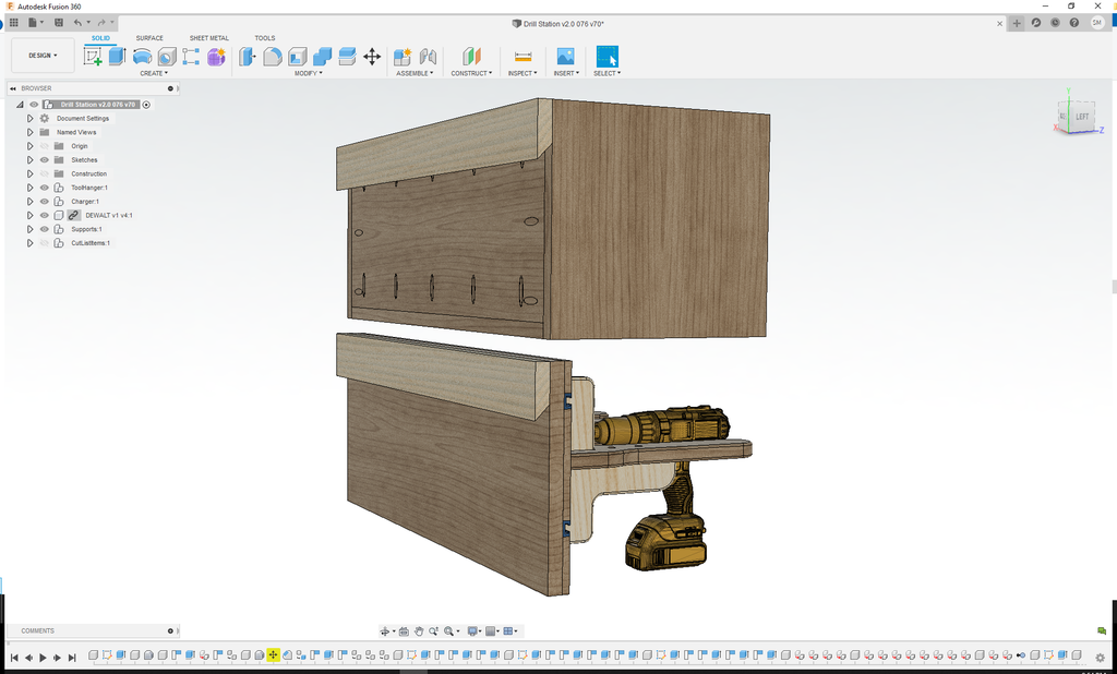
After designing the tool holder I added storage above the holder with a simple box that can hold chargers and batteries for the tools hanging below. I also added some 2-1/2" diameter holes in the bottom of the box in the back corners. This allows the cord for an outlet strip to feed out of the bottom of the box and supply power to the different chargers.
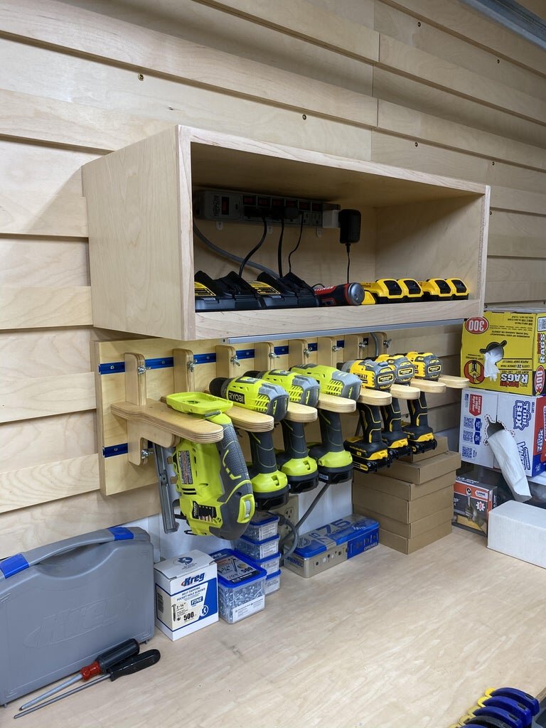
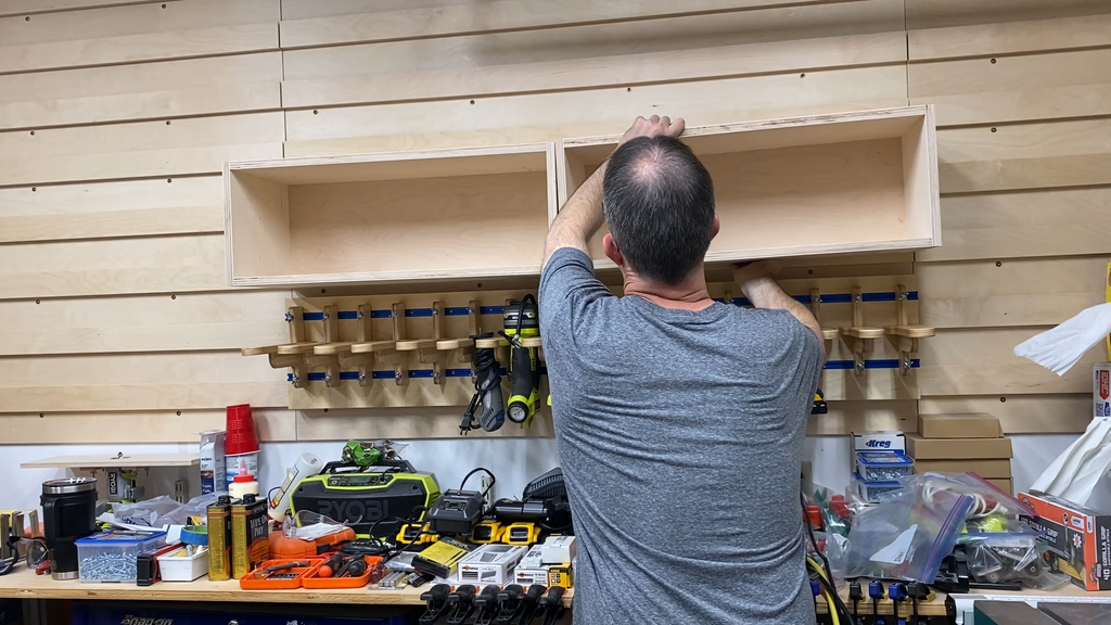
One thing you will notice is that I made the Tool Hanger and Tool Charger separate. This makes it easier to build them and also gives you the flexibility to use one or the other or both at that same time.
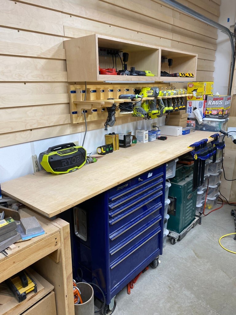
Step 3: Cleat Wall System
This tool charging station was designed to be used with the cleat wall I installed on my garage wall. You can still build this project if you don't have a cleat wall. You can install it directly on your wall or you can hang it on your wall with individual cleats.
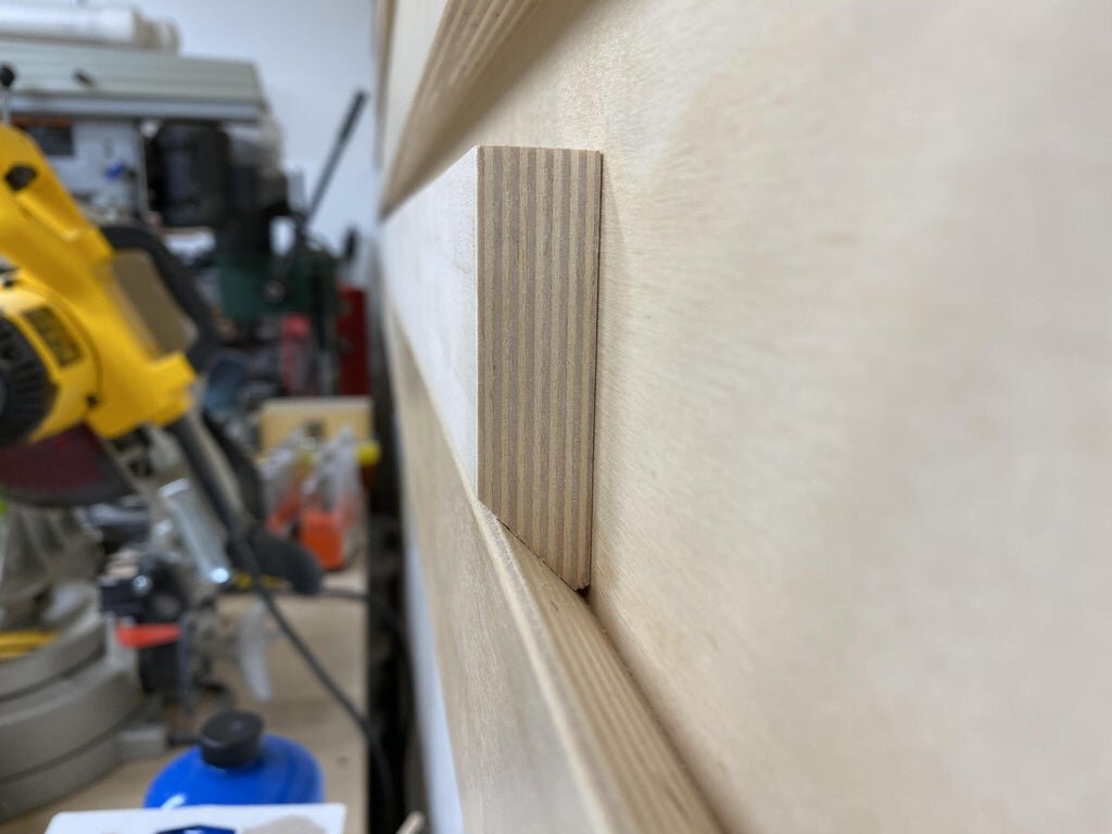
My cleat wall was designed using 5' x 5' x 3/4" thick pieces of baltic birch plywood. The cleats are spaced at 6" in the vertical direction. This way the tools can be moved easily in the left and right direction and up or down every 6 inches. The cleat wall was also designed in panels that are 60" tall and 30" wide in order to make installation easier. Because of that, I decided to make the tool charging station 30" wide. You can easily make it 48" wide or another width by adjusting the width of the pieces accordingly.
The french cleat is 3/4" thick x 2-3/4" tall on the long side of the cleat. The angle of the cut is 45 degrees. I did cut the very tip of the cleat off as this last little bit is prone to breaking off. The other reason to remove this little tip off of the cleat is that if there is any debris or obstruction (like sawdust) in the upward facing cleat on the wall then when you place the opposing cleat down into it there is a chance the cleat you are placing into it will not rest all the way down on the bottom cleat. That can also put a point load on that little obstruction and not distribute the weight of the item you are hanging on the cleat.
Step 4: TOOL HANGER:
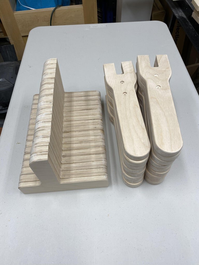
Cutting the Tool Holders - by Hand or CNC
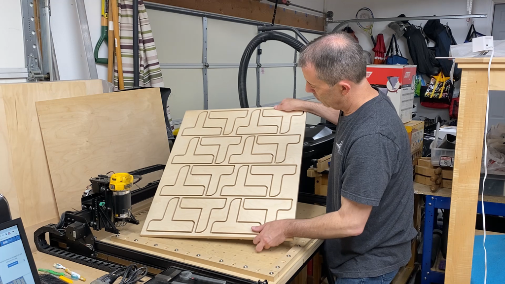
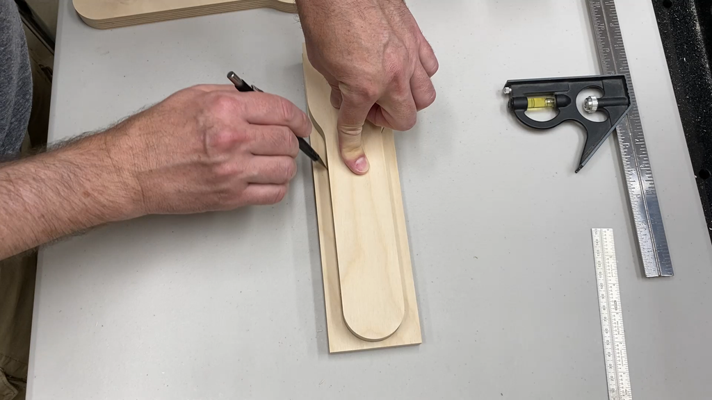
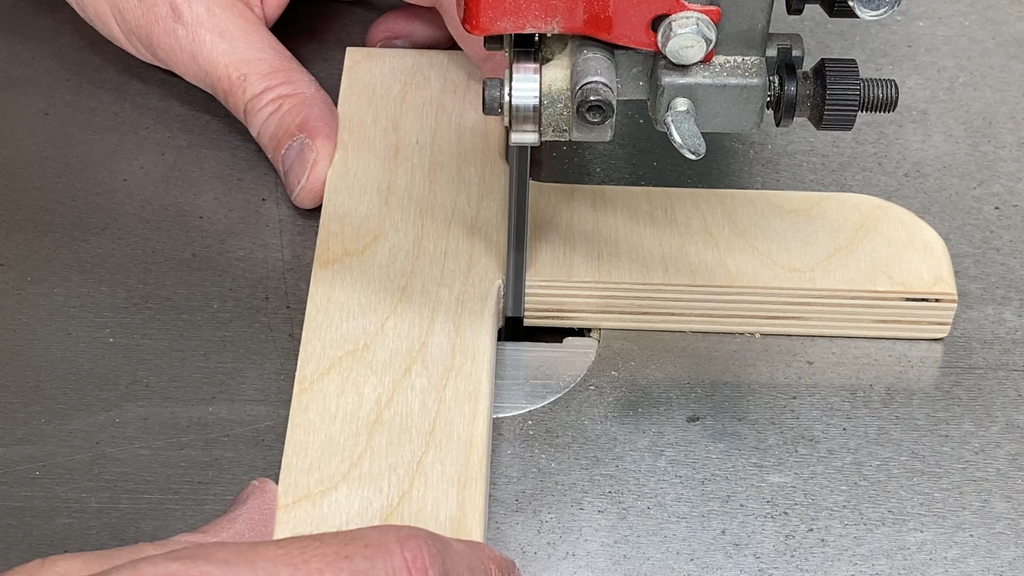
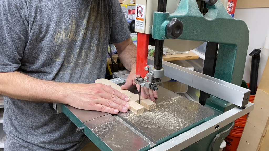
I designed the tool holder pieces so you can cut them out with a regular tools, such as a band saw, or cut them out with a CNC. Full size templates for the tool hangers that you can print are included in my plans.
Take your time to layout the shape of the two tool holder pieces. One you cut one of each you can use them to trace outlines for duplicates. If you do cut out templates then you can just use thinner material, like 1/2" or 1/4" plywood, to trace the outlines on to other pieces.
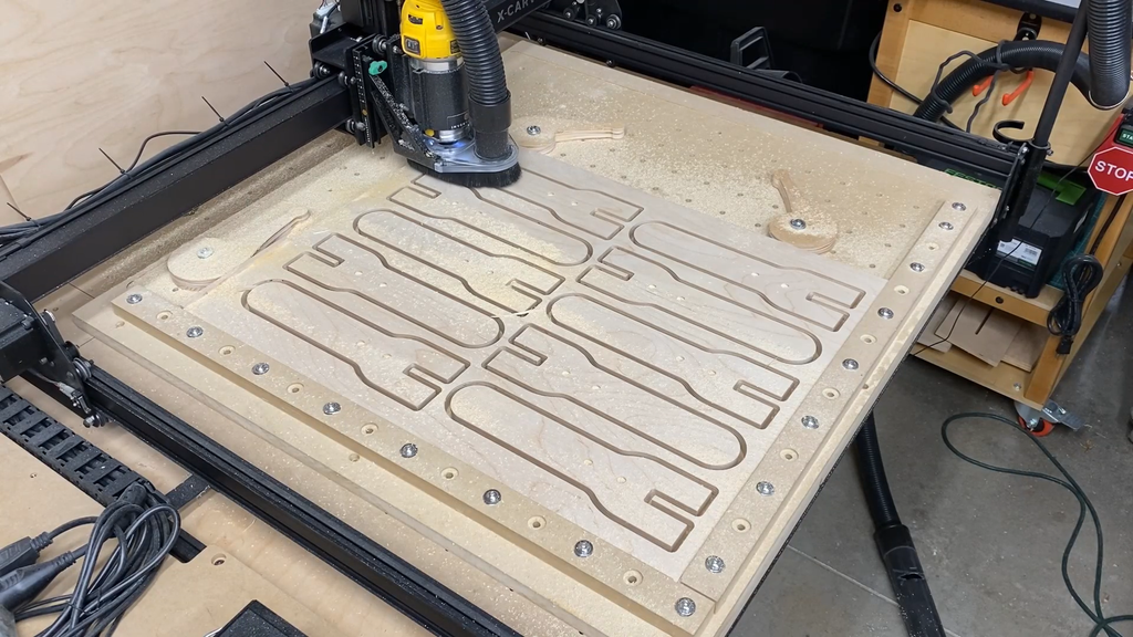
I used an X-Carve CNC machine to make easy work of cutting out the two different shapes that make up the tool holder. If you cut out the shapes and use tabs to hold the pieces in place then there is very little clean-up work.
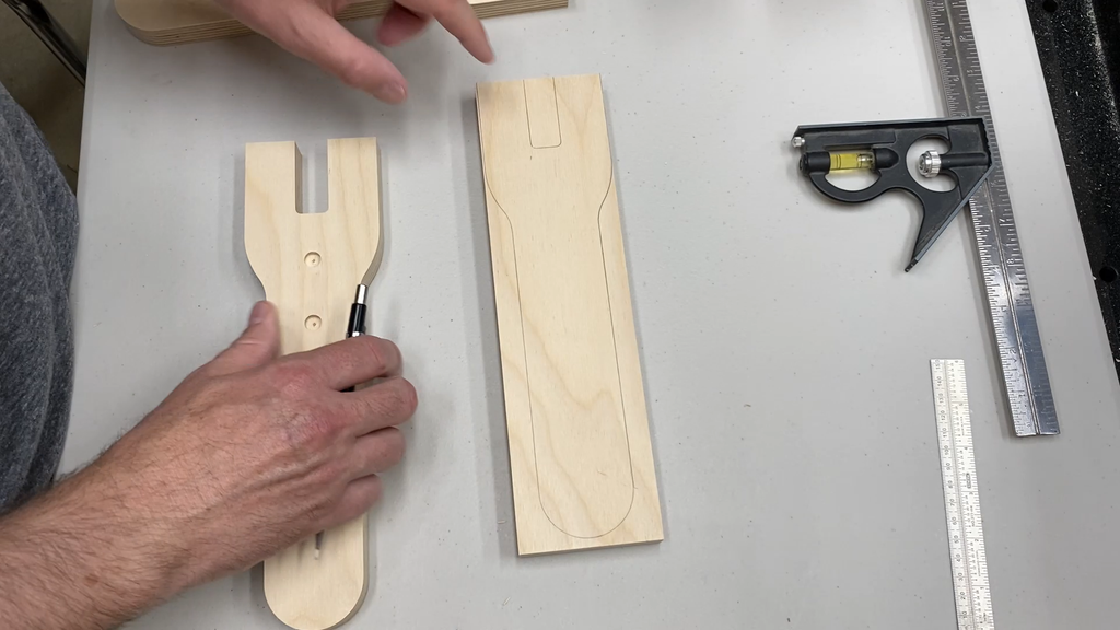
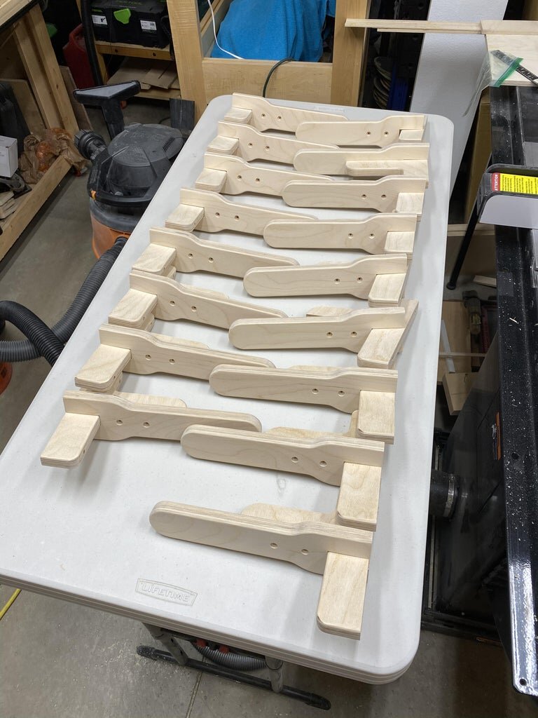
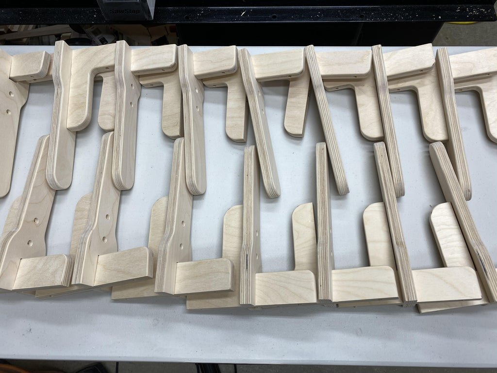
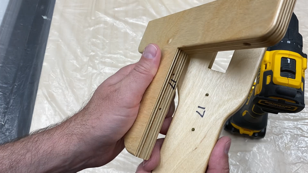
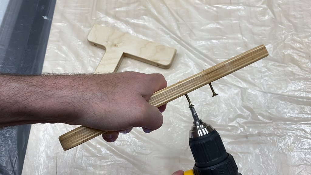
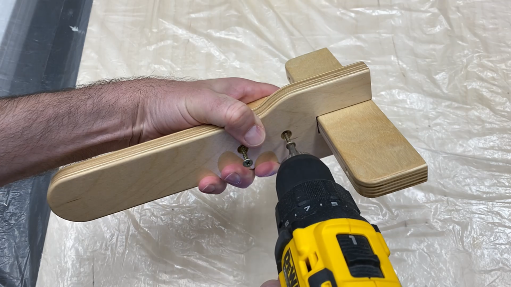
There is a little clean up work to get the tool holders screwed together. I recommend marking each piece with matching numbers so you can keep the pair together in the process.
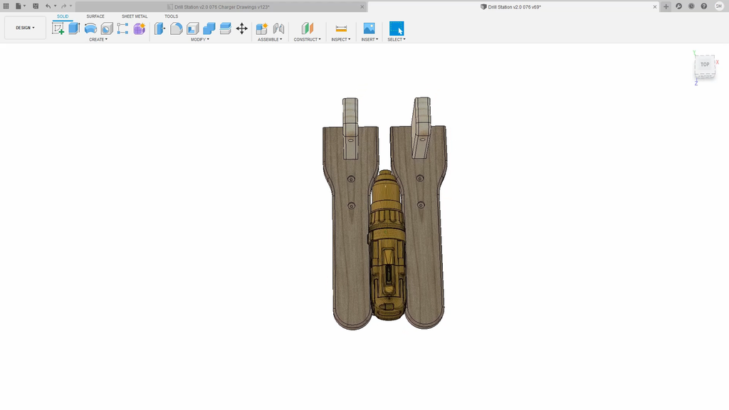
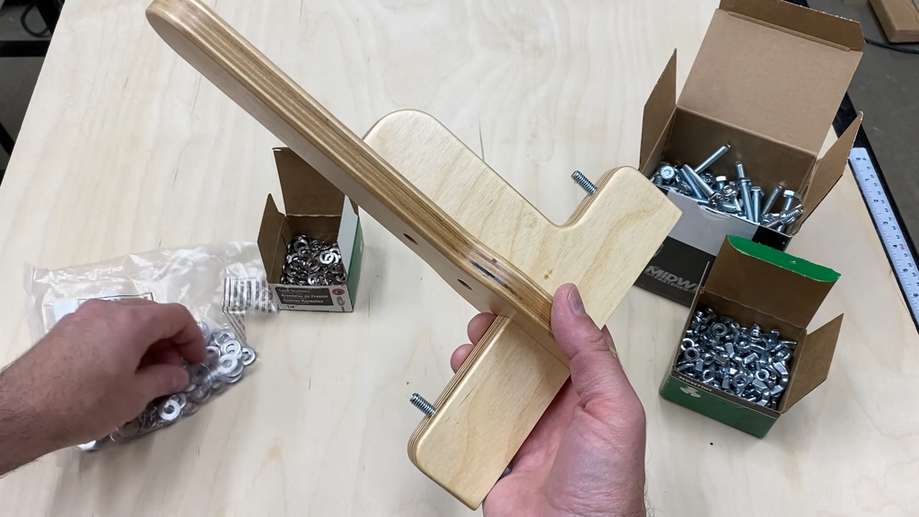
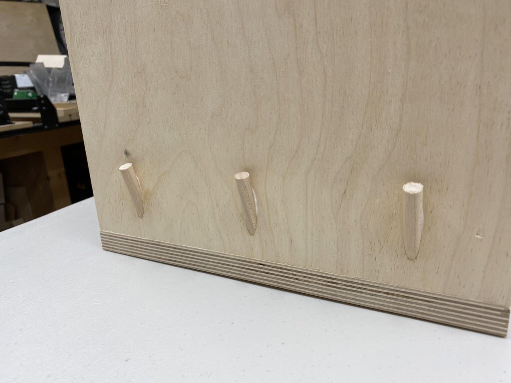
You want to make sure that the Tool Hanger Bottom piece is able to slide up and down in the Tool Hanger Top piece as shown in the picture.
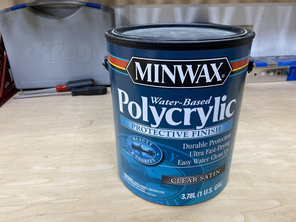
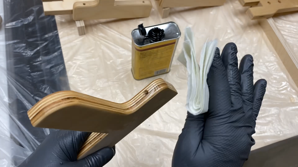
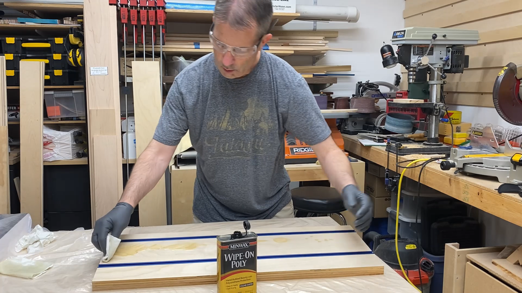
Once you have the pieces all cut out and sanded, you will need to add some finish. The Tool Hanger Top and Bottom pieces are only screwed together so you don't need to worry about gluing them together later.
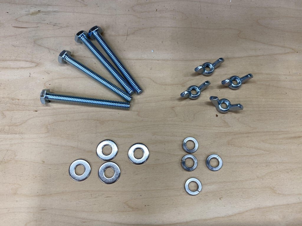
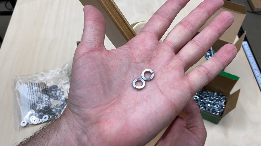
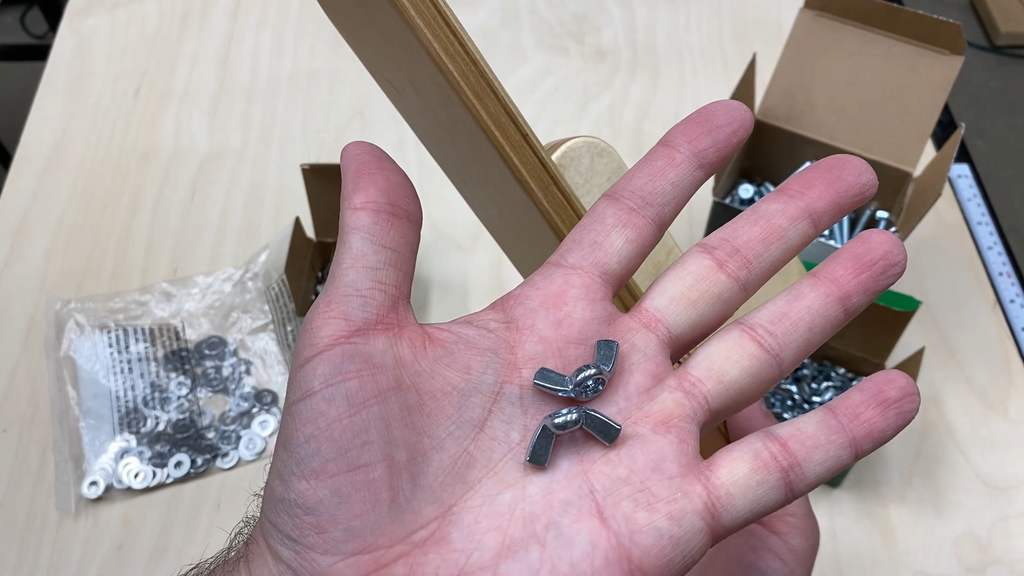
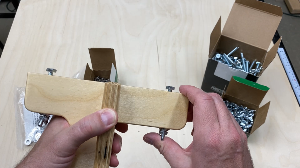
After the finish dried you can add the hardware. Each hanger gets two of the following:
1/4" diameter 20 tpi bolt at 2-1/2" long
1/4" lock washer
1/4" flat washer
1/4" wing nut
Step 5: Cutting the Back Piece, Kreg Mini Trak, and Spacers
The back piece, or support, for the tool holders is made with one piece of 3/4" thick plywood with the other pieces attached to the front face. The pieces attached to the top are alternating pieces of 3/8" thick plywood and Kreg Mini Trak, which is also 3/8" thick.
All of the plywood pieces are cut in rectangular shapes to make for an easy assembly.
I cut the back piece to final width and cut the height at 1/2" long so I could cut it to the final height once the other pieces were glued to the face.
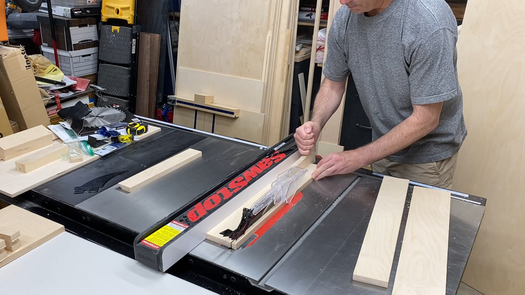
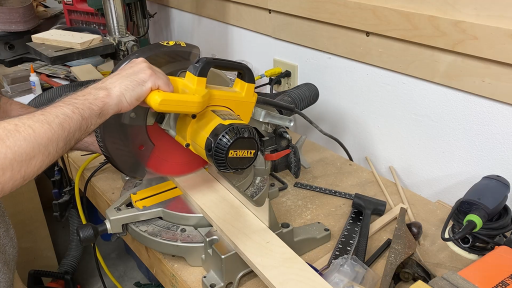
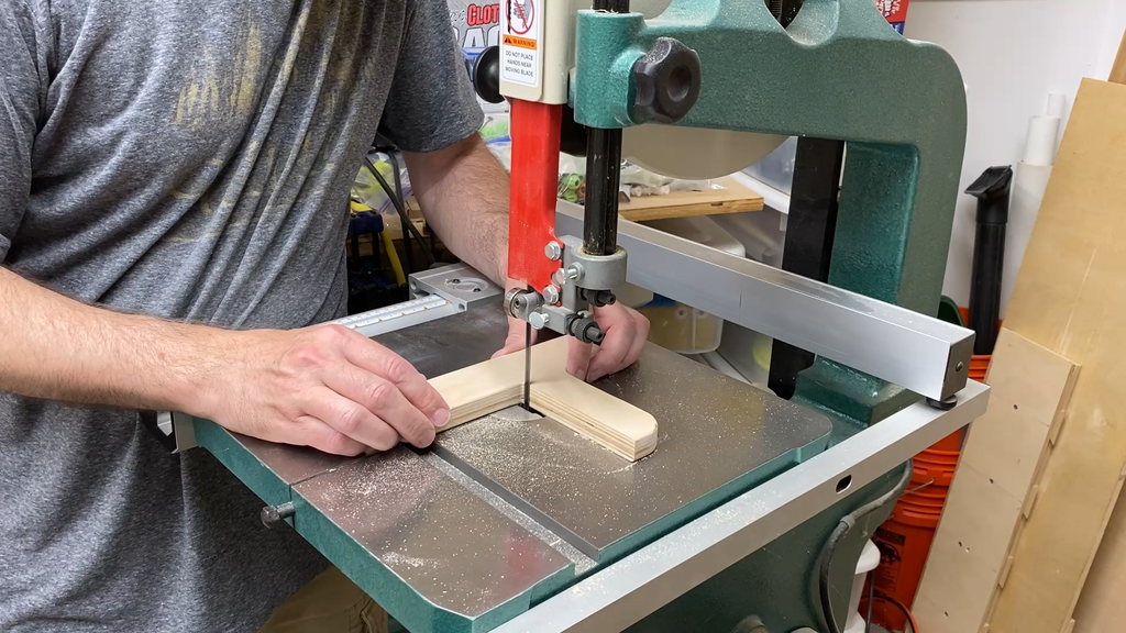
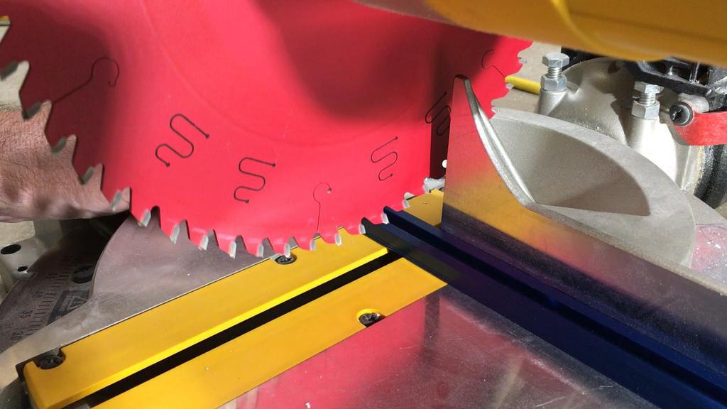
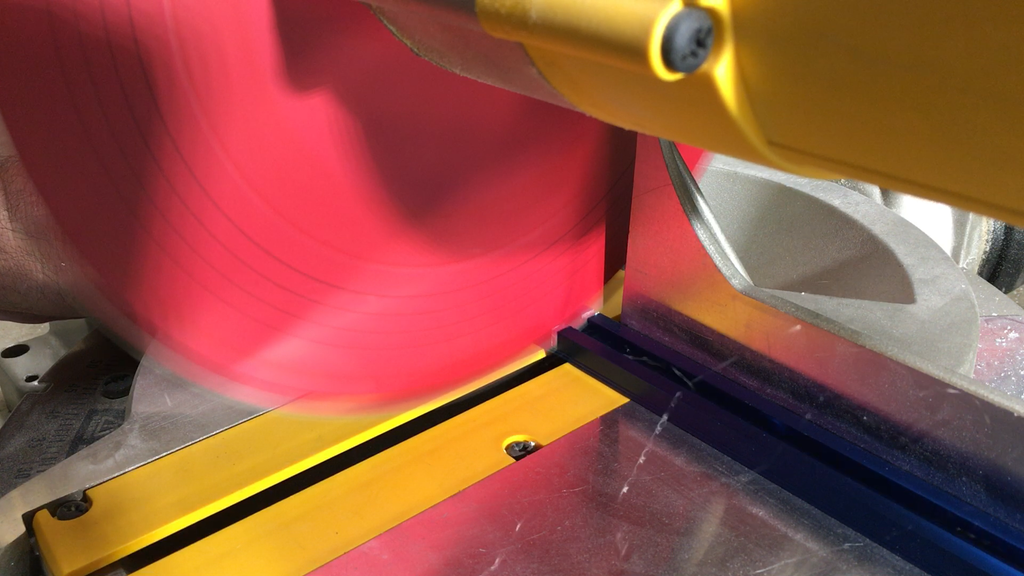
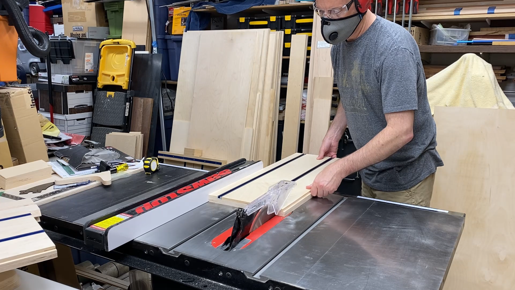
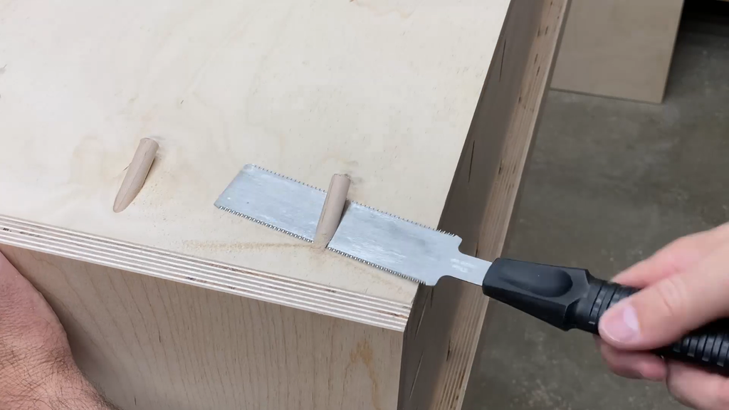
I used my miter saw to cut the Kreg Mini Trak to length. The Mini Trak can be cut with a regular woodworking saw since it is aluminum, but only do this if you are comfortable with the process.
NOTE: Make sure you are not trying to cut the metal with a flesh sensing saw like a Saw Stop or it will trigger the brake.
SAFETY NOTE: Make sure you were eye protection when you are using power tools, but especially when you are cutting metal. The metal flakes can fly all over the place and you don't want a piece ending up in you eye. Since I needed two pieces of Mini Trak at 30" long, I decided to center the piece I needed so the remaining screw holes were centered. I realized if I had cut a 30" piece off of one end of the trak I would end up with one of the screw holes right at the end of cut piece. The cut pieces on the end of the aluminum track can be very sharp so it is a good idea to use a file to clean up the edges. You may also need to file a little bit off the inside edge of the trak where the bolt heads slide through so they slide cleanly through the opening.
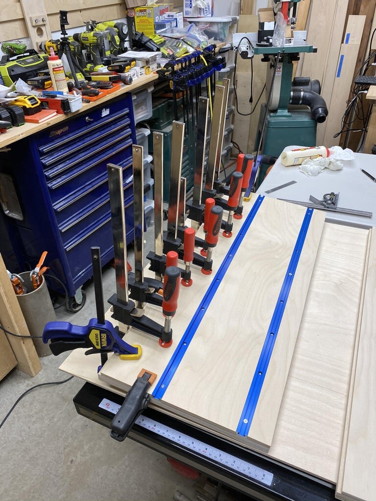
The idea behind the spacing of the Kreg Mini Trak was to make the dimension exactly 6" between the center of one trak to the other. Since the Mini Trak is 3/4" wide then you need a piece in between the two tracks at 5-1/4".
The top piece I cut to the exact width needed.
The bottom piece I cut 1/2" taller than necessary since I planned to cut the assembly off to the final height once it was fully assembled.
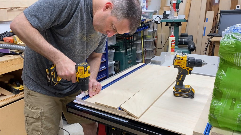
Step 6: Assembling the Back Piece
In assembling the back piece, I glued the top piece of 3/8" plywood the the 3/4" thick backer first.
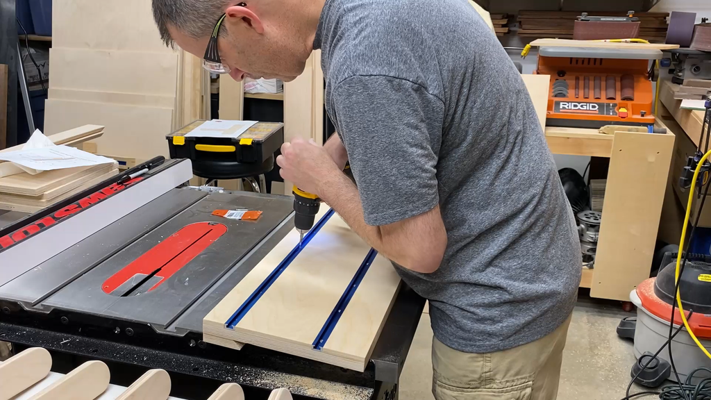
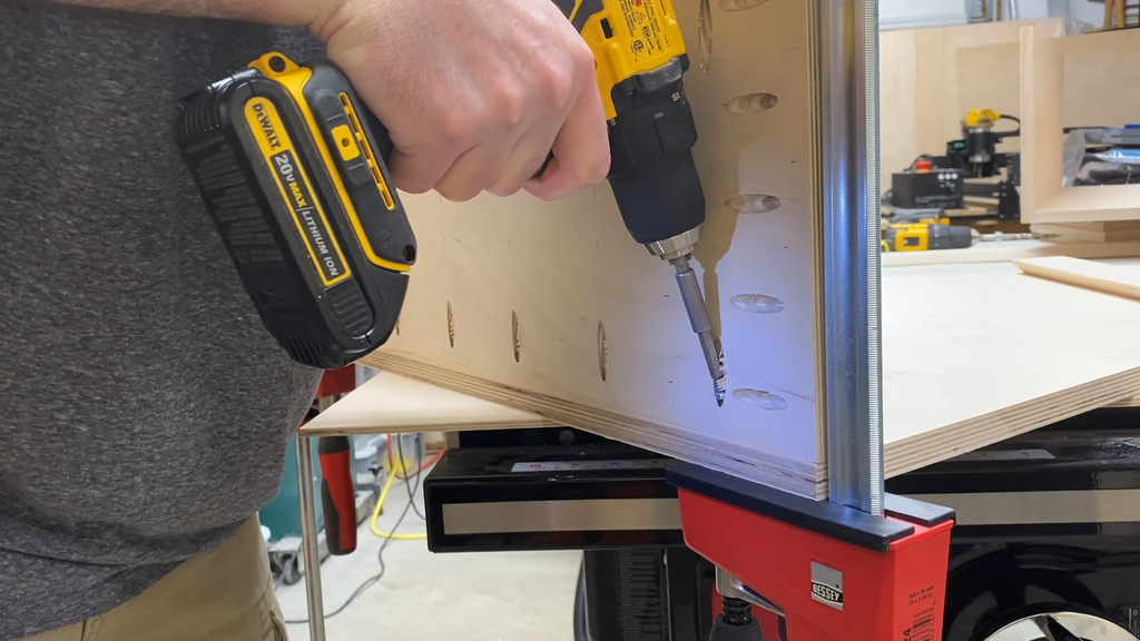
Next I screwed the top piece of Kreg Mini Trak to the 3/4" backer piece with #6 x 3/4" screws.
Holding the middle piece of 3/8" thick material in place I screwed the second piece of Mini Trak in place.
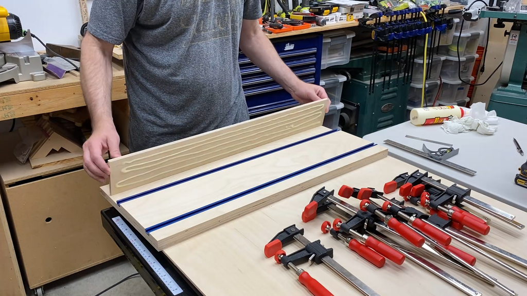
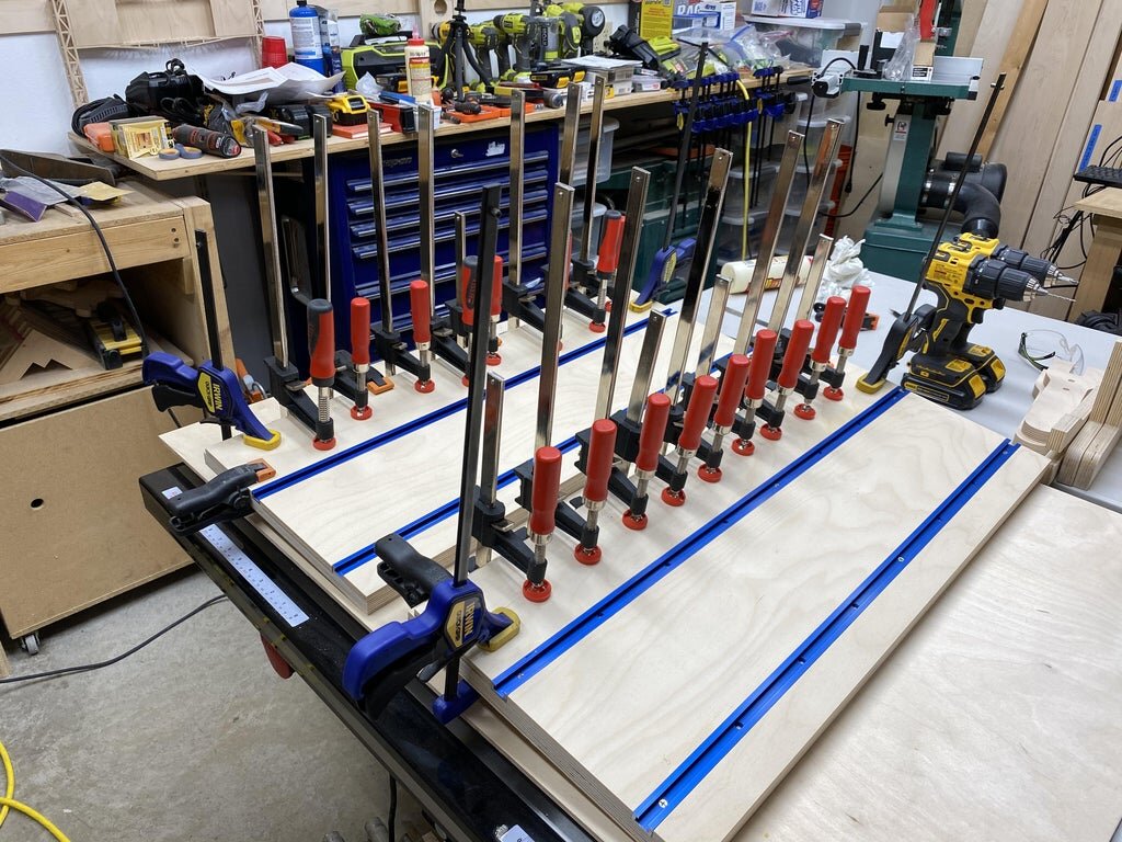
Next I glued the middle piece and bottom piece of 3/8" material in place.
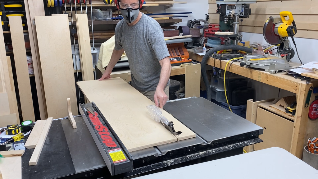
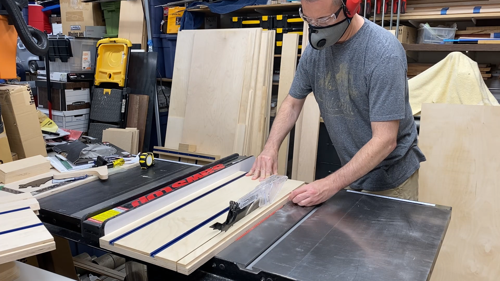
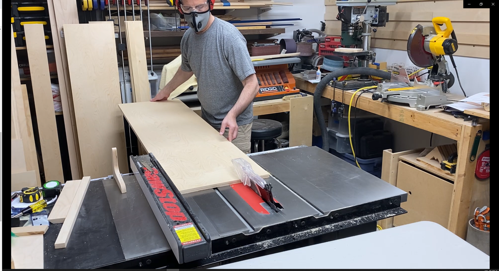
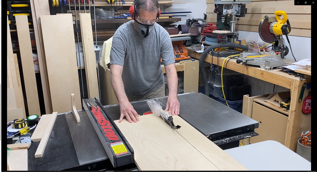
After the the glue had set I ran the whole piece through the table saw (with the trak facing up so it wouldn't get scratched) to cut off the excess from the bottom of the assembly.
Lastly, I glued and screwed the french cleat to the back of the piece. You will notice that the top piece of Mini Trak is located so the screws holding it in place can be changed to 1-1/4" long screws for extra holding power. This isn't necessary on the bottom Trak as the screws for this track don't have to do as much as compared to the top track which has the tool holders pulling out on them.


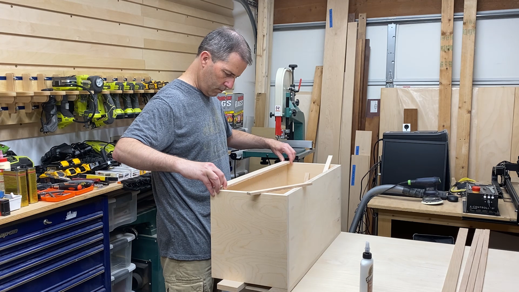
Step 7: TOOL CHARGER: Cutting the Box Pieces
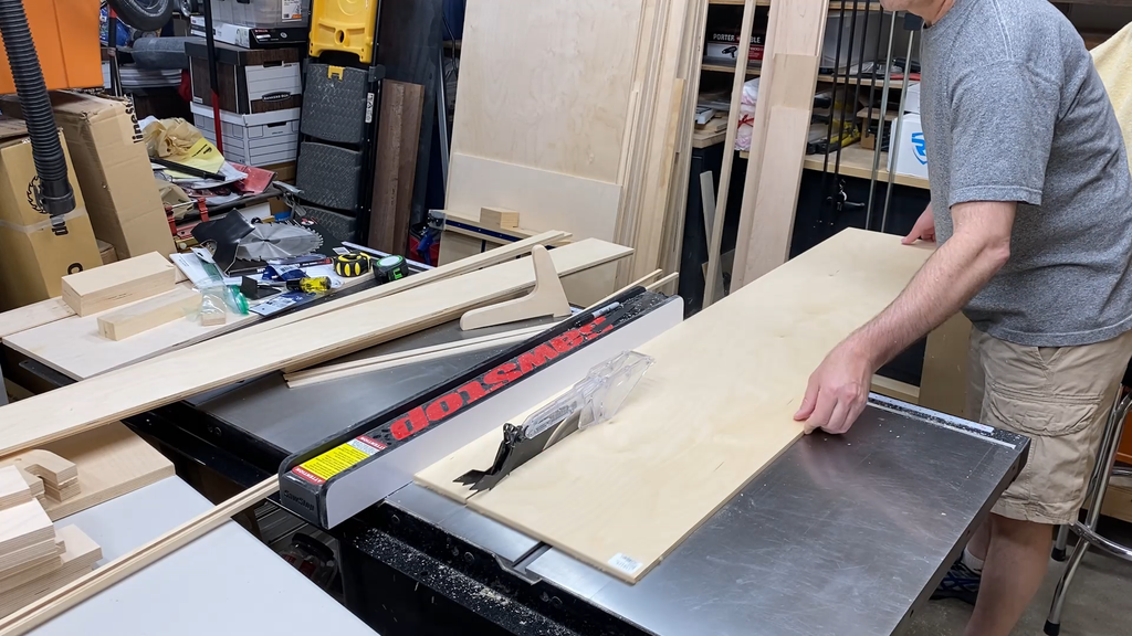
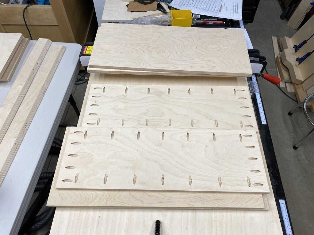
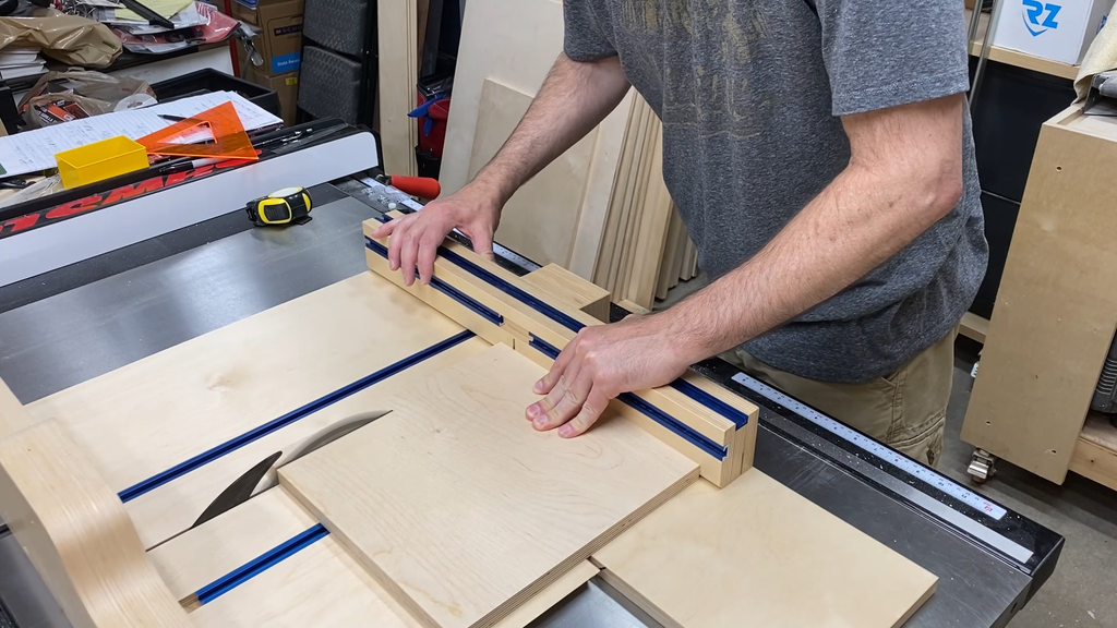
I cut all of the charging box pieces at the same time so that widths and lengths matched for a better assembly. I did leave the box sides a little long so they could be cut the final necessary length later.
Make sure you cut the top (Piece A), back (Piece B), and sides (Piece D) of the box at the same time so they all have the exact same 12" depth.
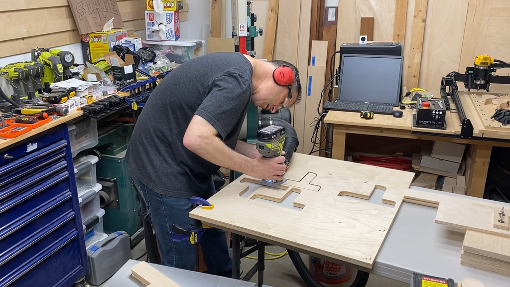
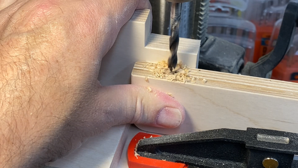
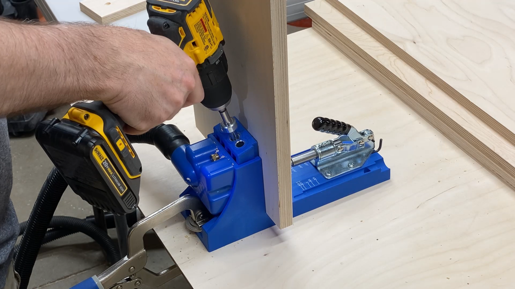
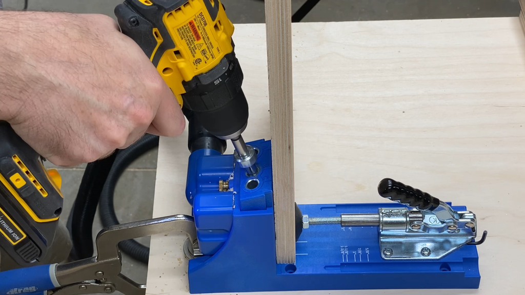
Step 8: Drill Pocket Holes
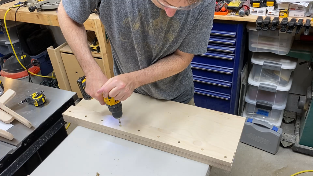
Now that you have all of the piece cut to size you can drill the pocket holes in the pieces for a quick assembly. I used the Kreg Tool pocket hole system. I have been using it for years and t works great.
Make sure to drill all of the pocket holes necessary before you start assembling. I forgot to drill the holes in the ends of the top and bottom piece and that slowed me down in the assembly process.
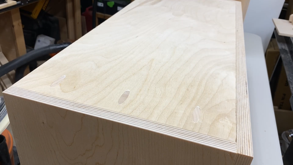
I also added a 2-1/2" diameter hole in the bottom back corners of the charging box in order to get power from lower outlets to the battery chargers. I decided to put one in each of the corners since I wanted flexibility on where the power would be coming from.
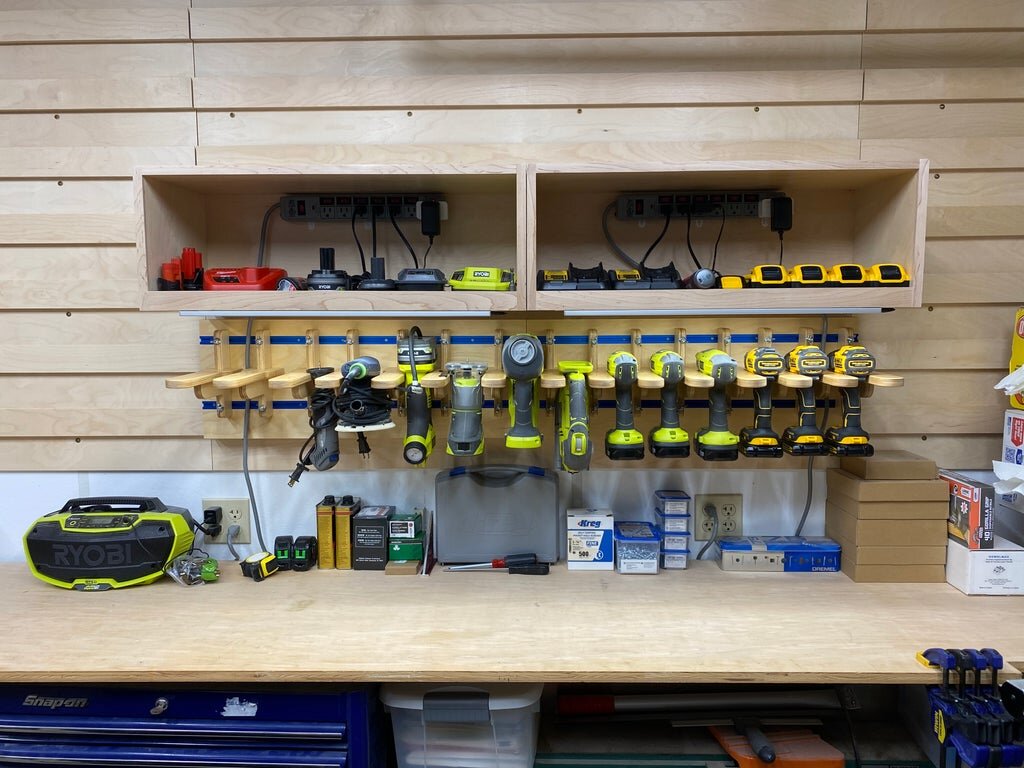
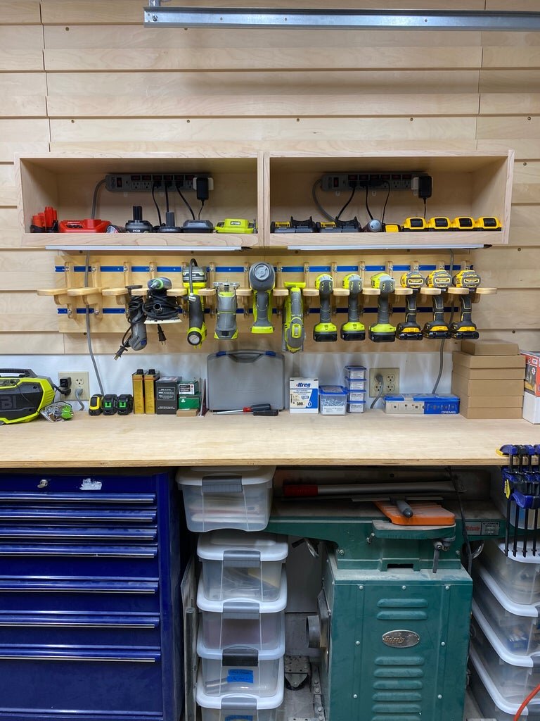
I also wanted to be able to run power from one box to another since I decided to make to of these to put side by side. I can run power out of one box an up into the adjacent box easily. I could have also drilled the holes in the side of the charging box, but this way it is hidden a little more and if I put something beside the charging box then it doesn't interfere with the charging cord.
Step 9: Assembling the Parts
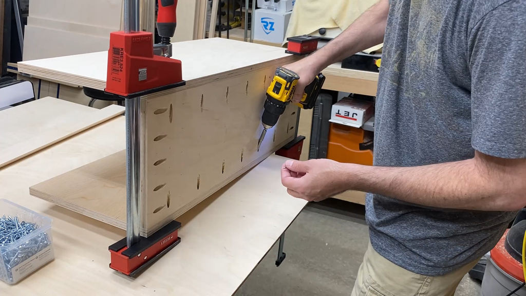
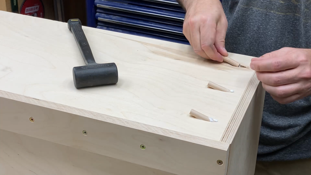
You can now use the pocket screws to assemble the charging box.
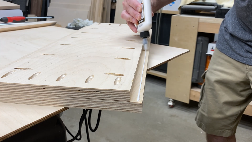
I started by gluing and screwing the back to the top and then the back to the bottom pieces first. Make sure if you added holes to the bottom piece that you position the holes towards the back piece.
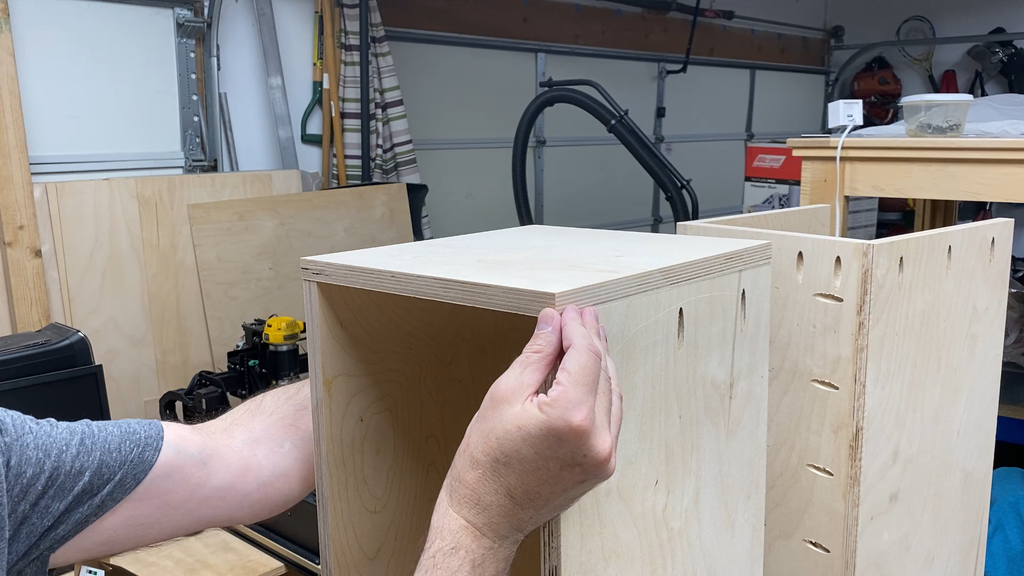
Next I measured the total height of the assembled pieces to determine what my side pieces needed to be and cut the side pieces to the appropriate length. Mine were just a hair under 11" tall. I had left these a little long when I originally cut them.
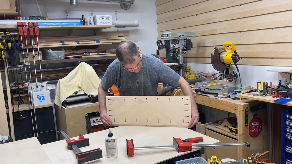
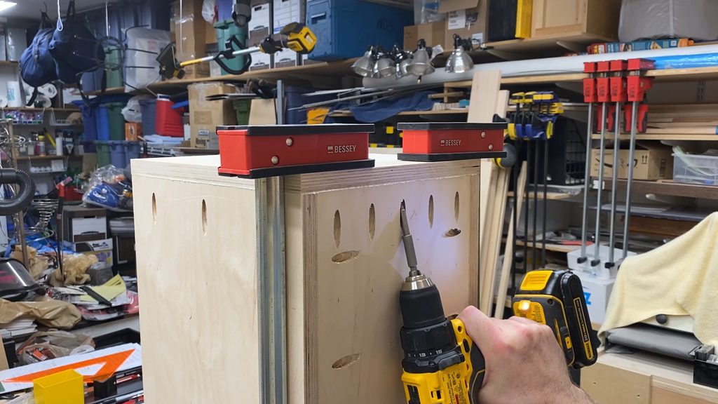
Next you can set the top, back, and bottom assembly on end and glue and screw one of the side pieces on the assembly. Once you have it screwed on you can remove any clamps you used, flip it, and add the other side piece.
The next thing you need to add is the french cleat to the back. I lined the top of the french cleat up to the top of the full box assembly to make it easier to assemble. I added some glue to the back of the cleat and then clamped it into position on the back of the box before I added 1-1/4" wood screws to give it some extra strength and to hold the cleat in position while the glue set up.
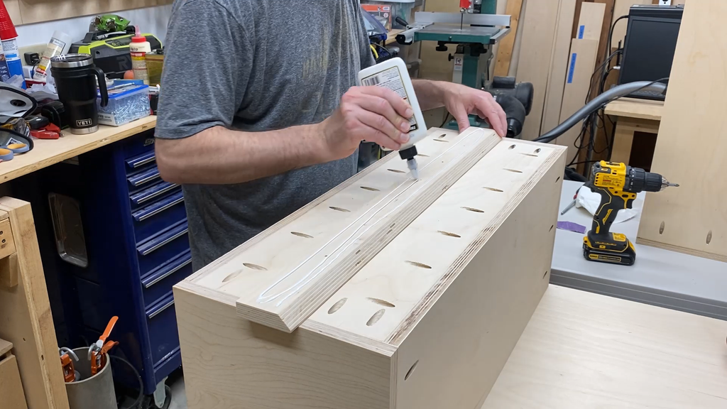

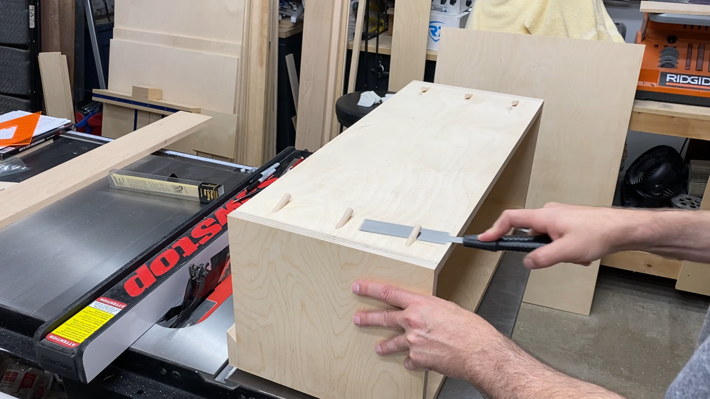
Step 10: Adding Solid Wood Trim on the Front
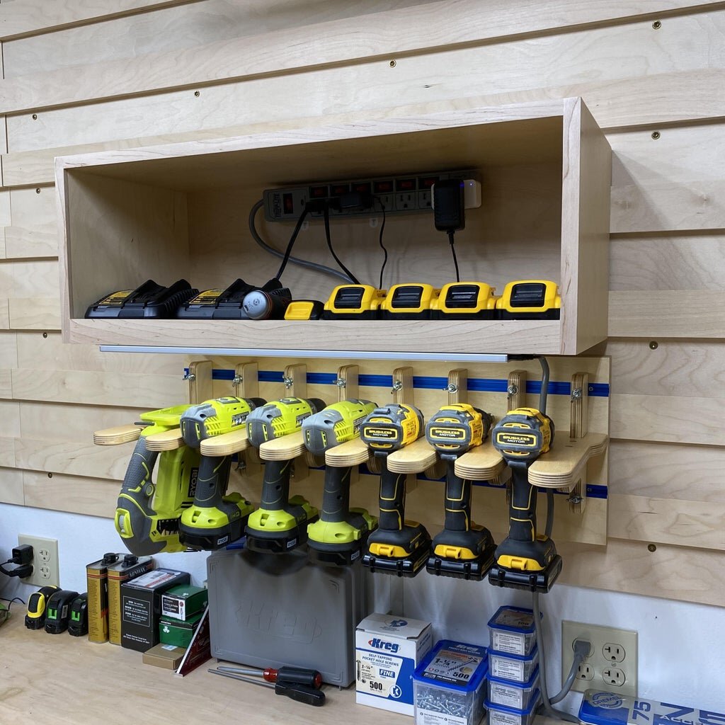
I added some pieces of 3/4" wide by 1/4" thick maple to the face of the charging box to cover up the plywood edges. This is not necessary, but I wanted to create a 3/4" lip on the bottom front to help keep chargers and batteries in place. In order to do this the bottom piece of maple trim was 1-1/2" tall by 1/4" thick. That created the 3/4" lip I wanted.
I glued the bottom and top edges first and then glued the side pieces in place.
Since most plywood is not exactly 3/4" thick, I did have a little bit of an overhang of the side and top piece of trim. I cut off the excess using a flush trim router bit.
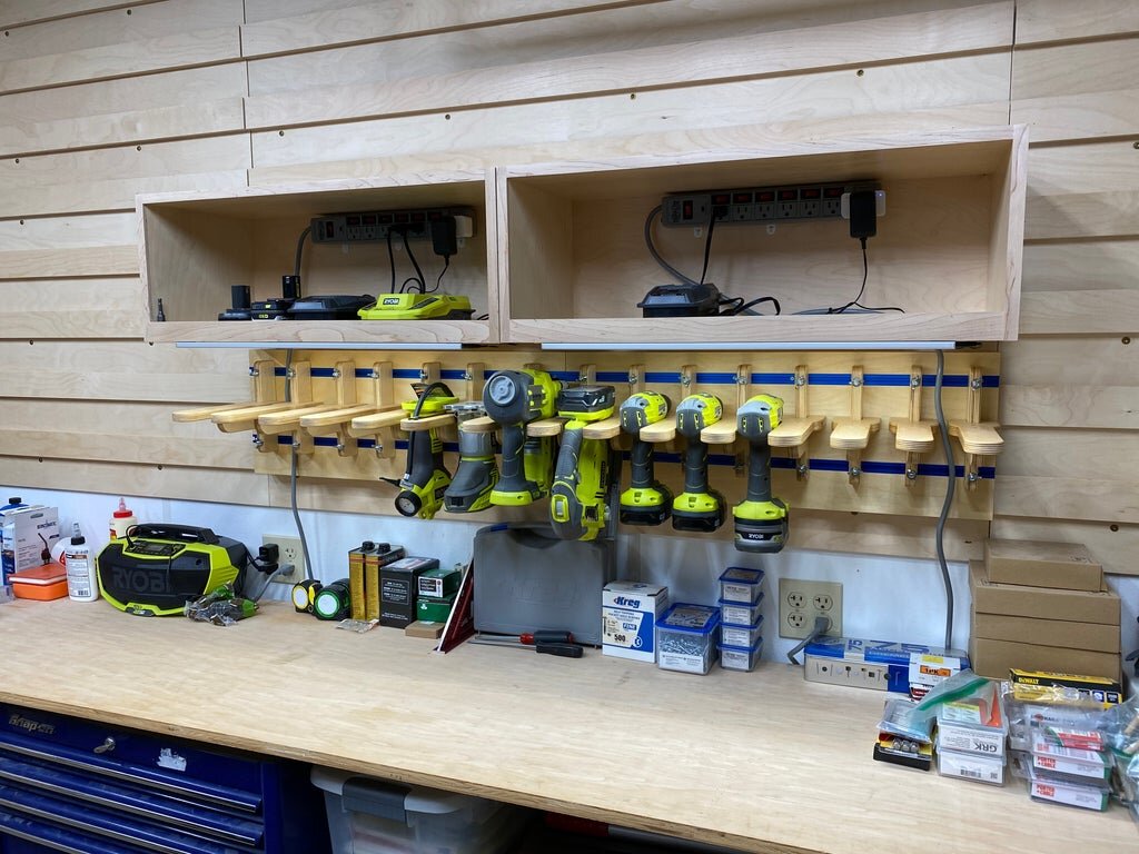
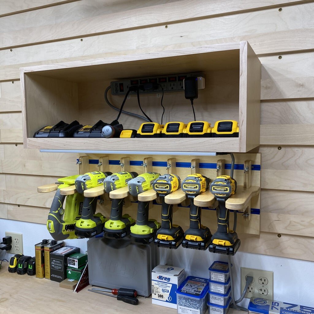
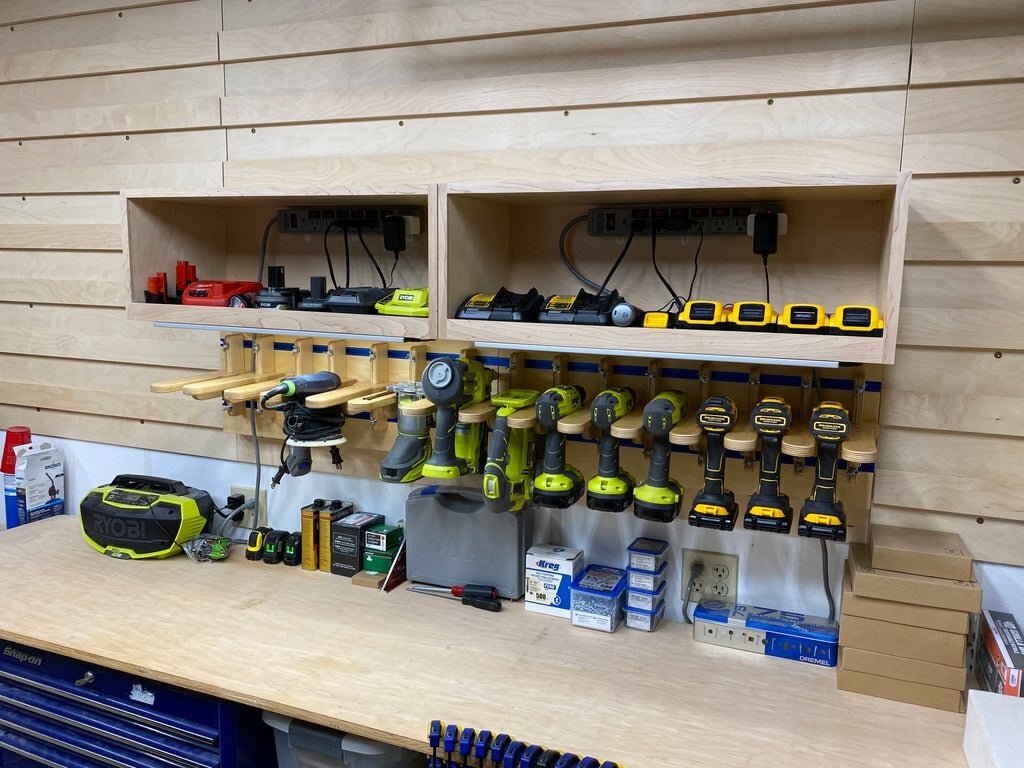
Step 11: Installation and Adding Tools, Power, and Lighting
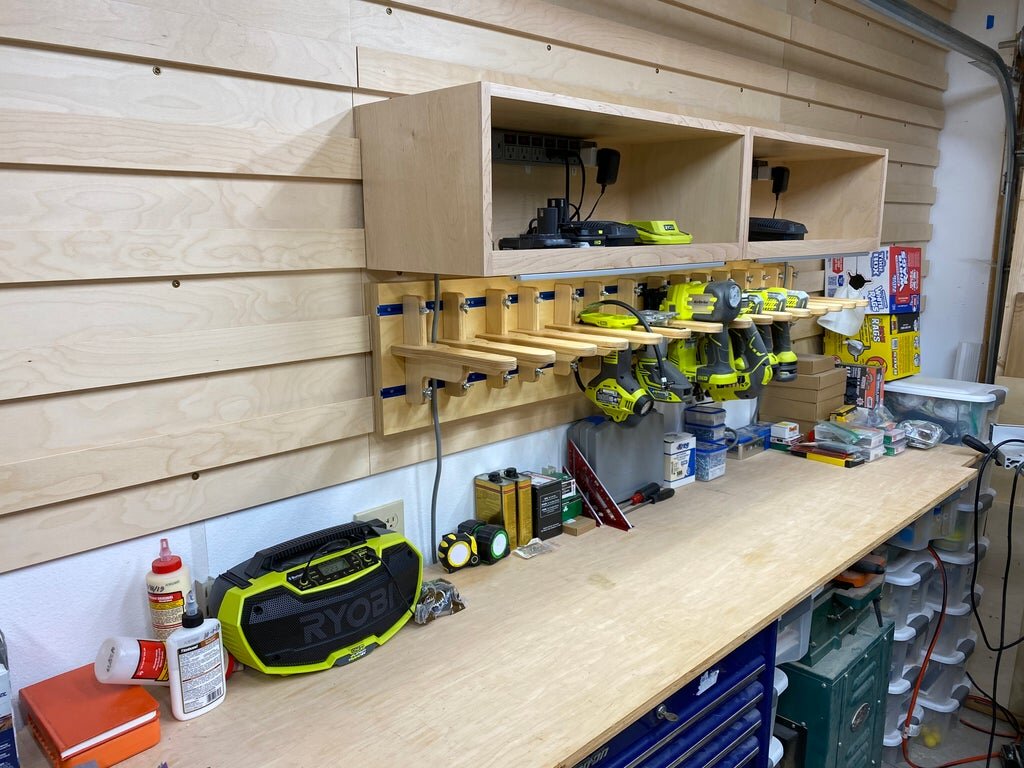
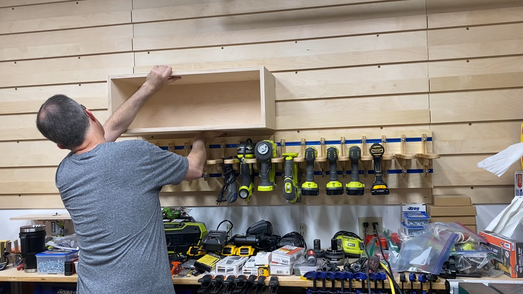
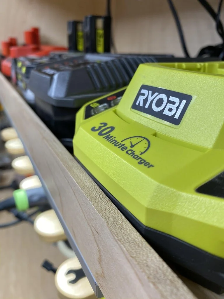
After sanding and adding a couple coats of water based topcoat, I hung the boxes on the cleat wall.
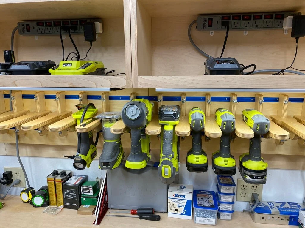
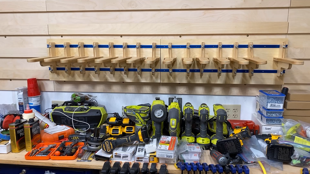
Next I started adding the chargers and batteries for the tools I had already added to the tool hangers.
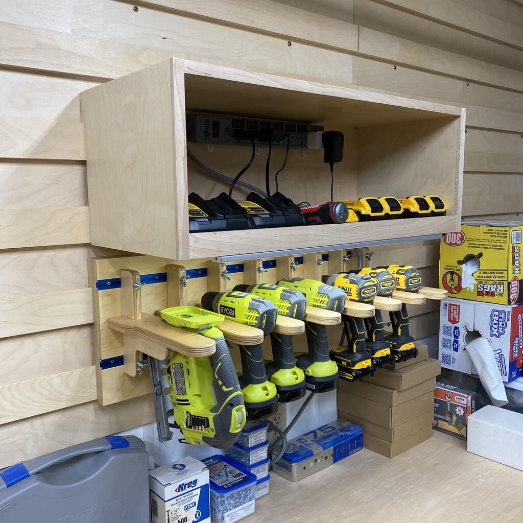
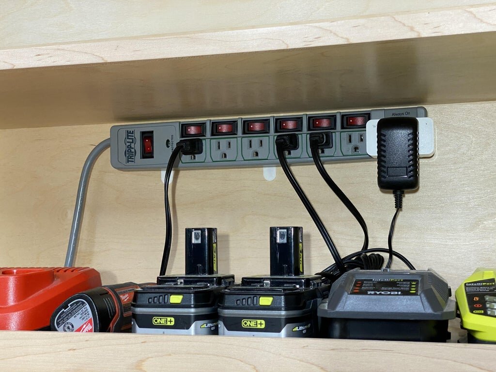
I added a couple of really great power strips in each of the charging boxes to give me better control on battery charging. These power strips have switches at most of the outlets so you can turn the power on and off to each of the chargers without having to plug and unplug them.
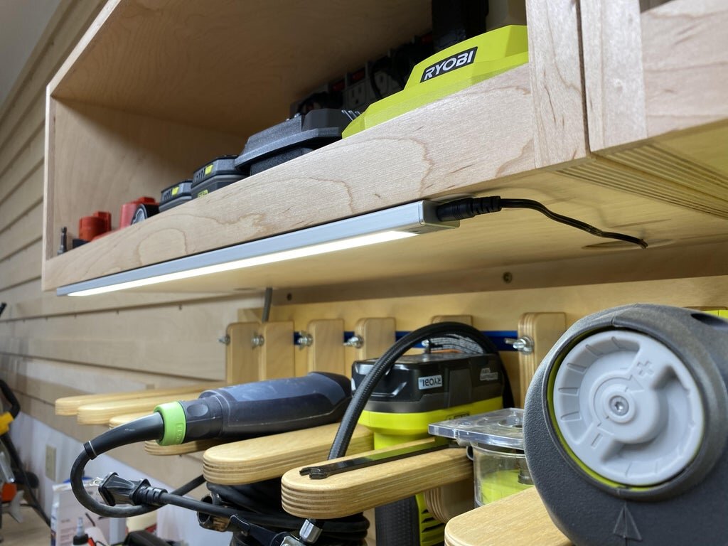
The last outlet on the power strip is always powered so this is perfect for adding some lighting. I also added an internet controller for the LED strip lights I added to the front of the bottom of the charging box. I used a Wyze brand web enabled controller that can be controlled by Alexa. I have it set up in my garage so that I can walk into the work area and say "Alexa garage on" and all of the overhead lights turn on. Now I can have a little more lighting under the charging box to light up the newly cleared work surface and it will turn on with my overhead lights! Yes, it's geeky, but I love it. Of course it's not necessary, but if you have an Alexa or other type of controller in your work area then it is really useful.
I initially hung the outlet strip and the LED light strip using 3M adhesive strips since I wasn't sure if I had things placed in their final location. It appears this will be strong enough to hold things in place permanently and I may not need screws to hold things in place.


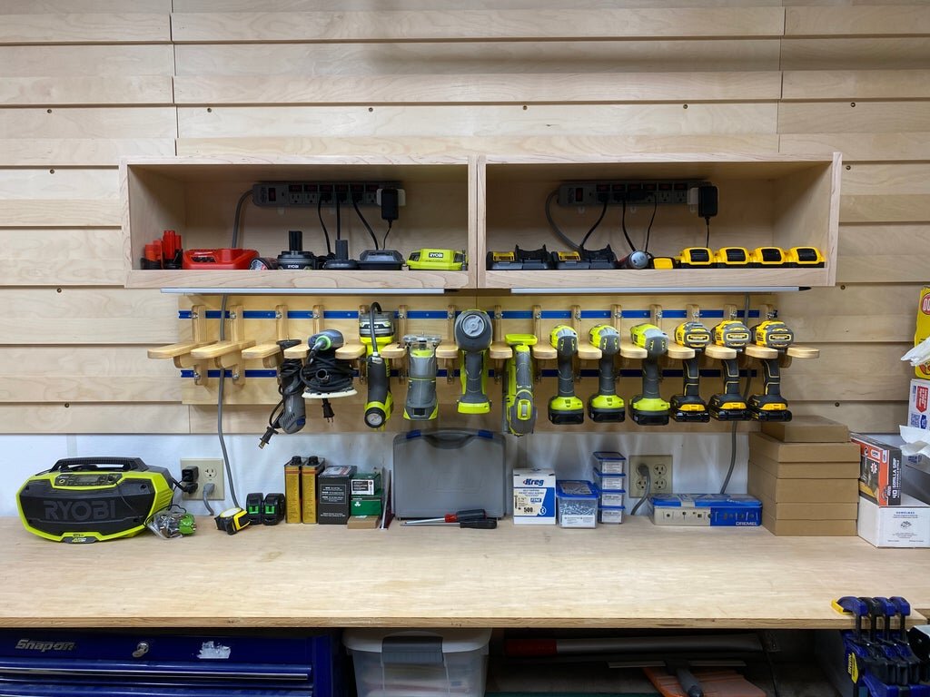
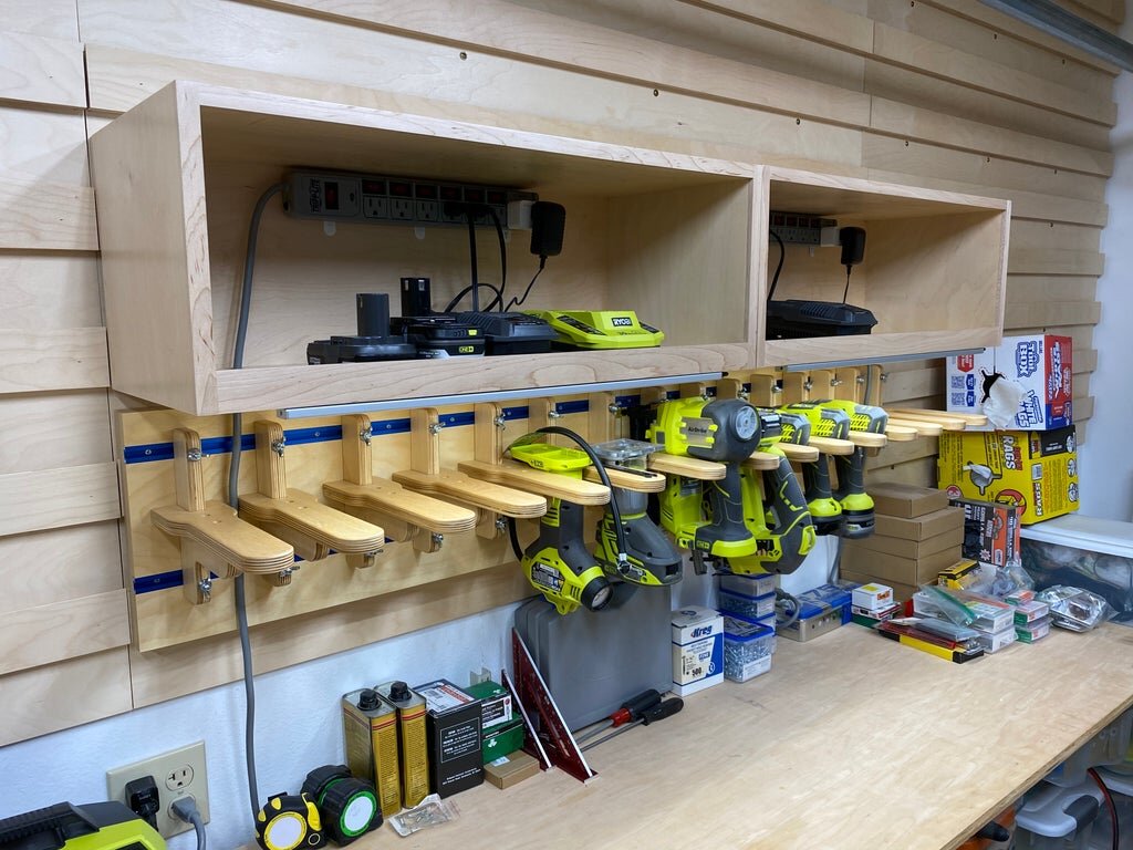
Step 12: Ready for Many Years of Use
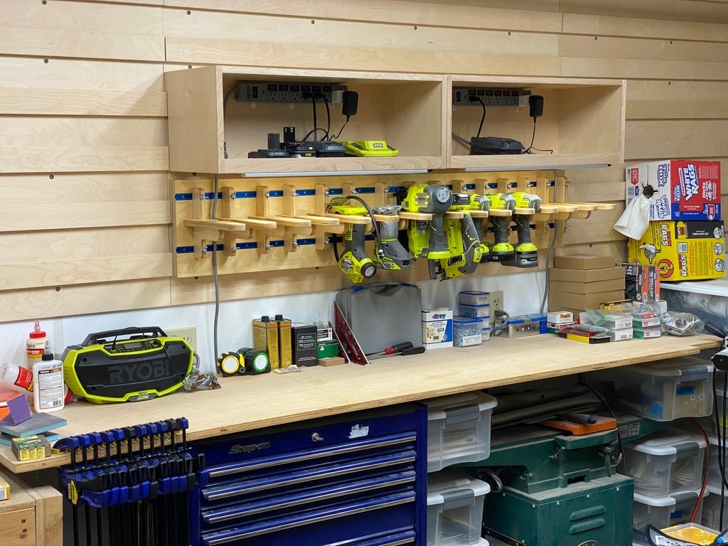
I am extremely happy with how the tool charging station turned out. I now have most of my hand tools where I can access them quickly and keep their batteries charged.
I don't plan on changing the spacing of the tool holders very often, but when I do I can do it fast and not have to cut new pieces. I also like having all of the chargers and batteries out of the way and where I can get to them easily.
If you like this project and want to see more then make sure you subscribe to my YouTube channel.
The next items I plan to add to the wall include the following:
Container storage for long term storage
Clamp rack
Sanding station
Pull down cabinet for higher items
General storage
Make sure you subscribe to my YouTube channel to follow along on future projects.
Click here if you want detailed plans and a cut list to build your own.